• Protip: Profile posts are public! Use Conversations to message other members privately. Everyone can see the content of a profile post.

***STICKY*** - Timing Belt & Transmission Rebuild Thread (2005 NSX 6MT)

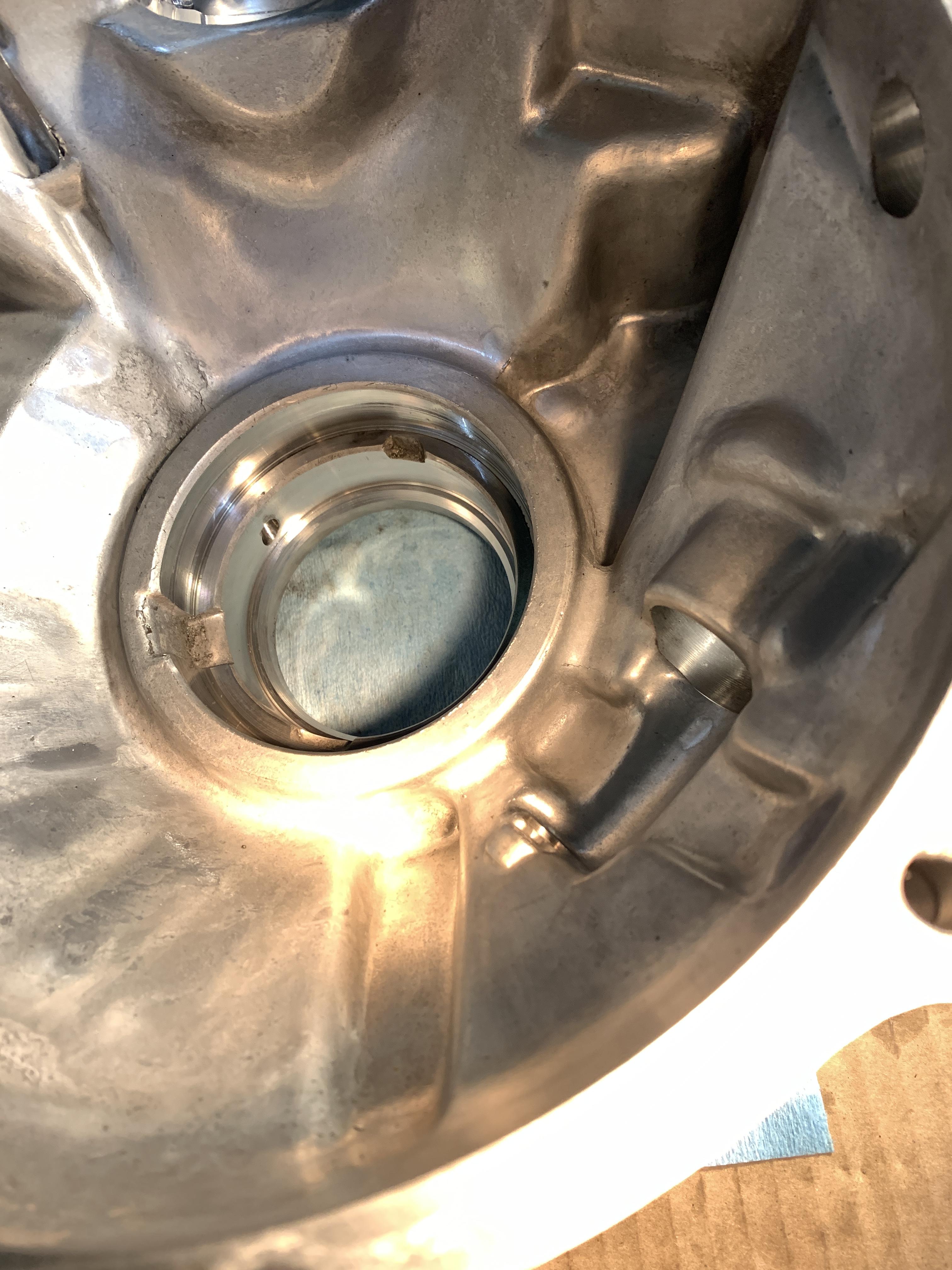
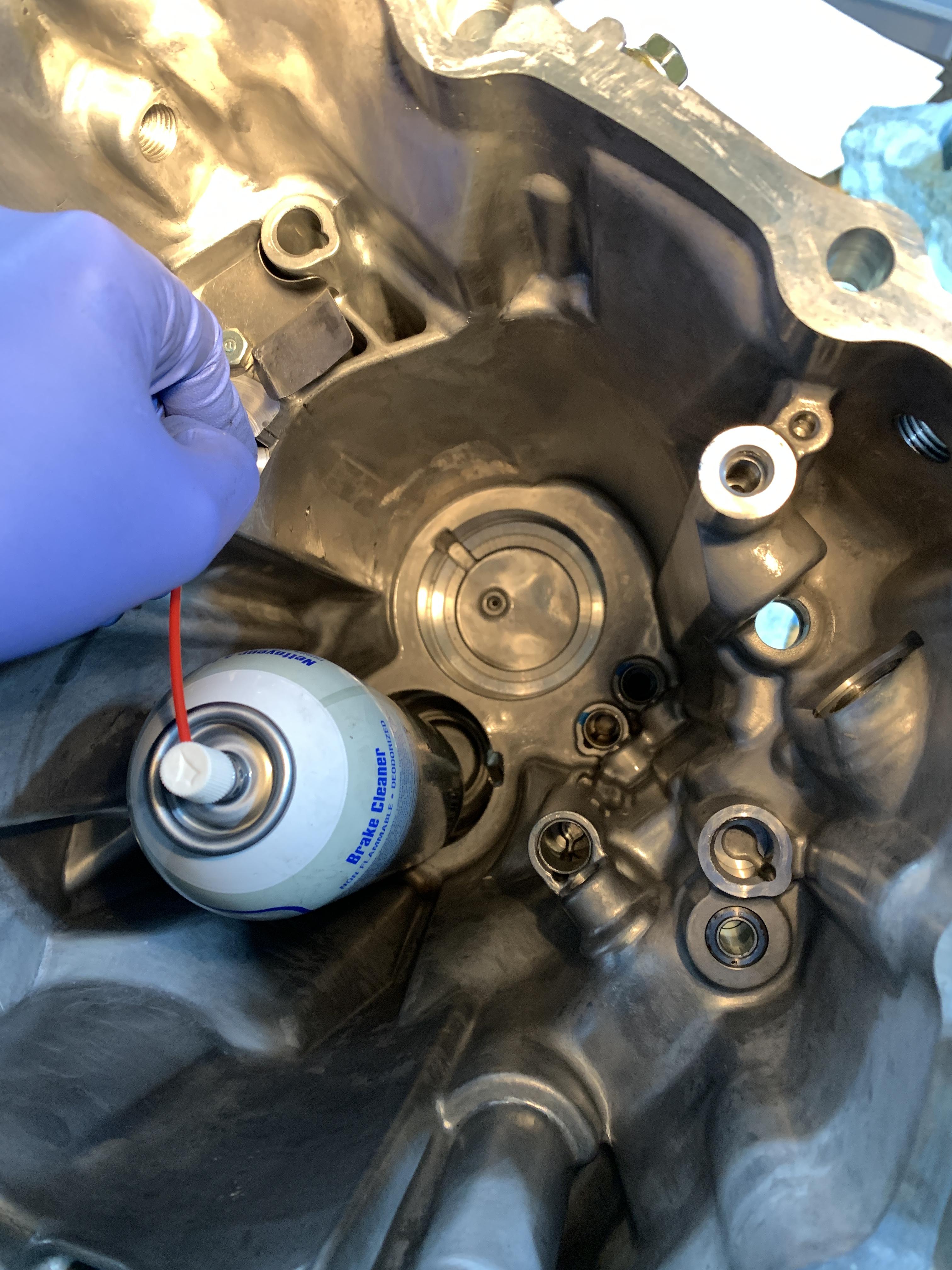
Now for the oil passages. I didn’t find any debris in any of the passages at all thankfully. The clutch housing side has 5 passages (more like 4.5). The transmission housing has 4 passages (more like 1).

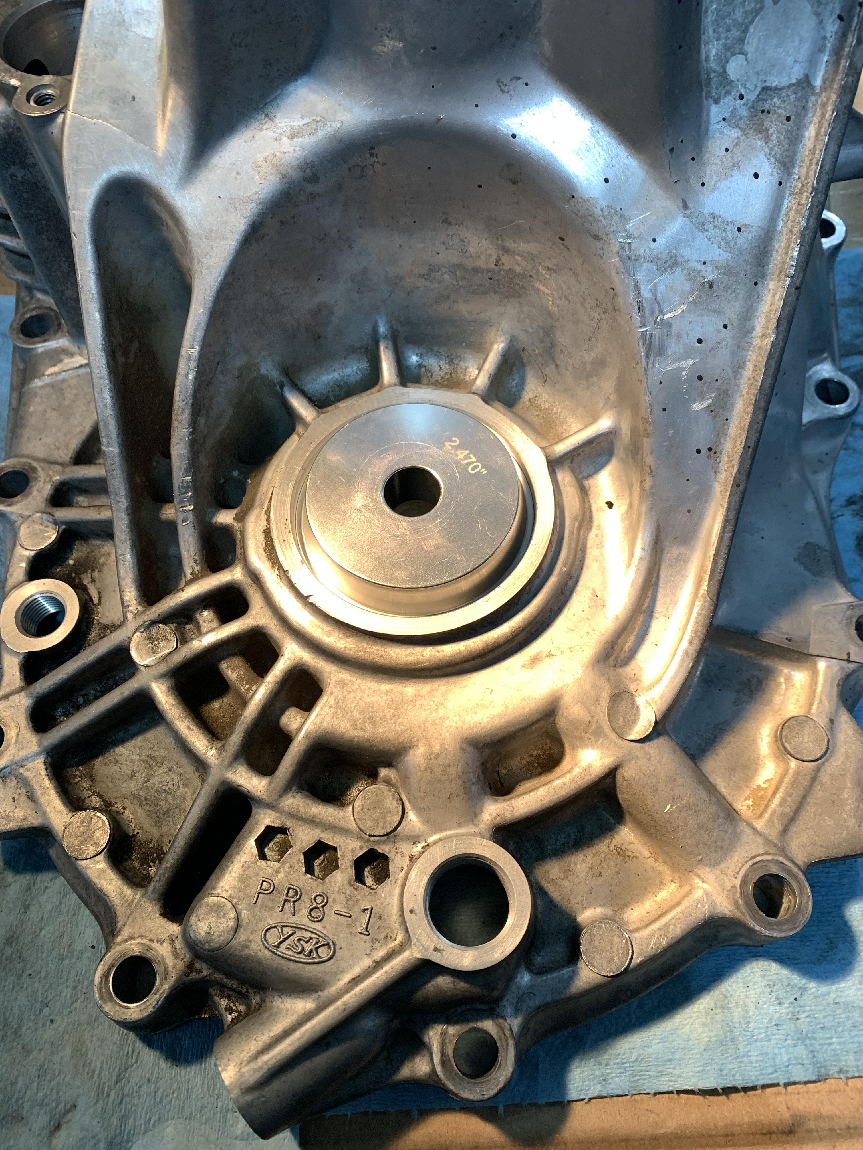
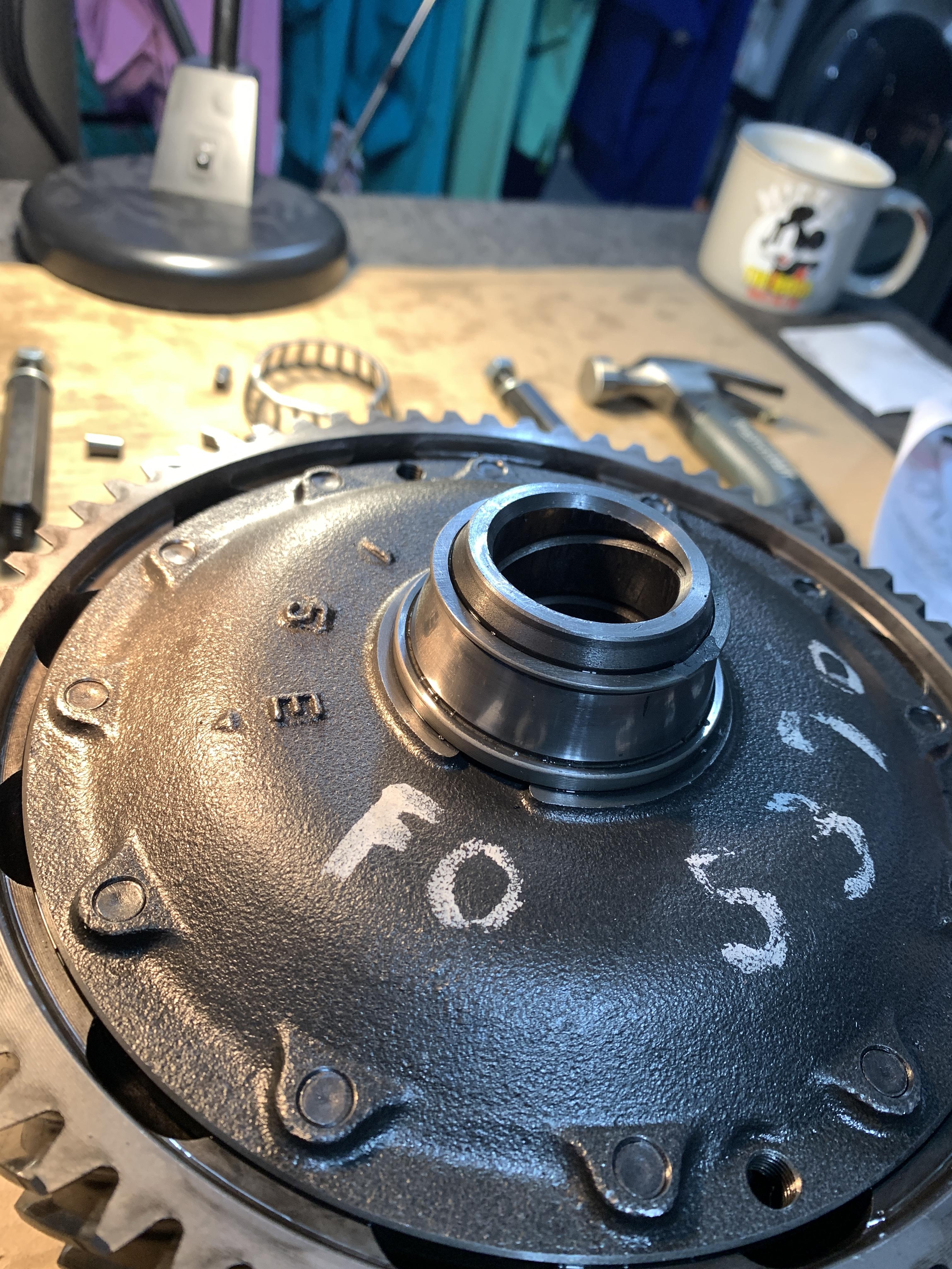
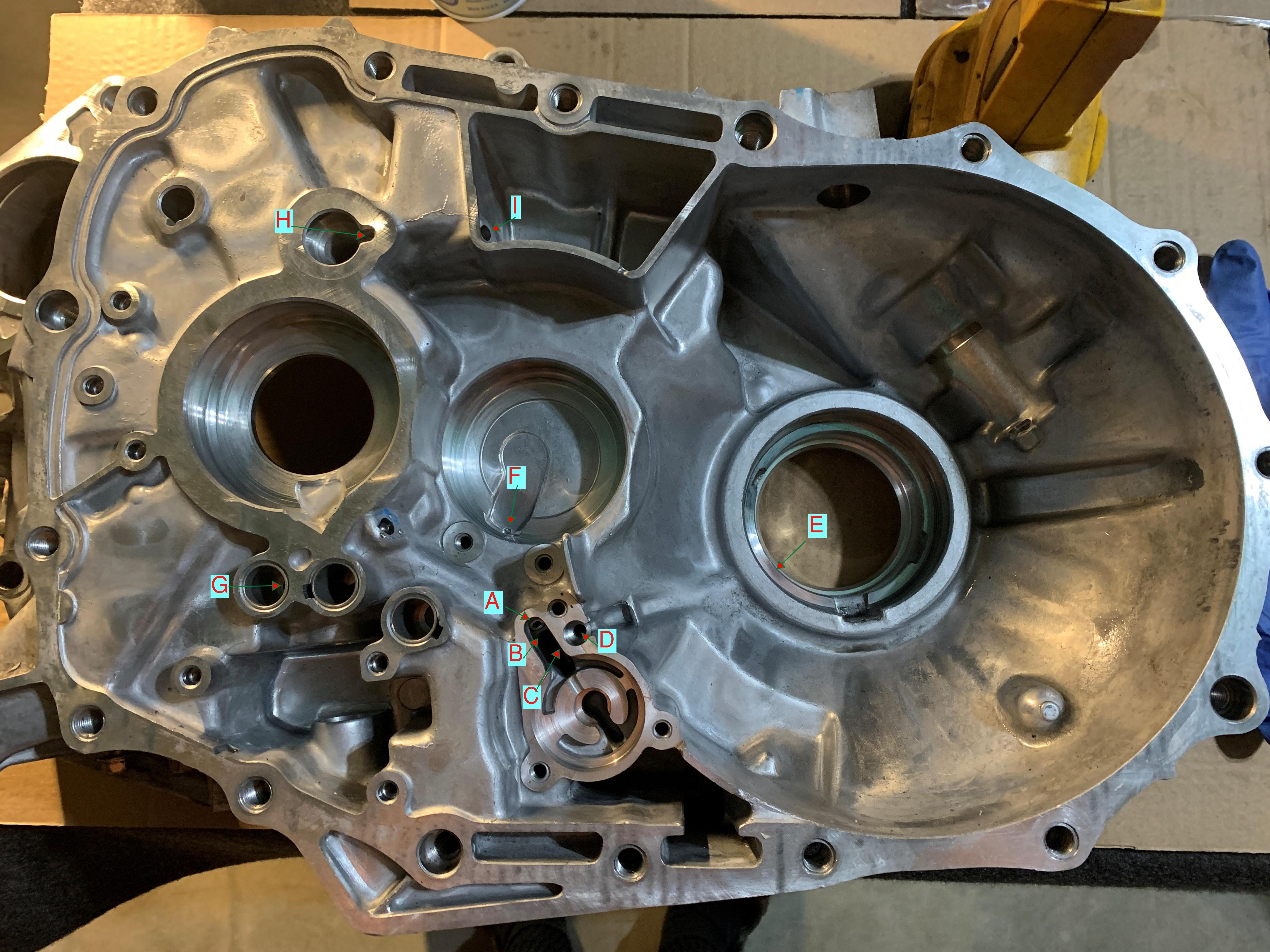
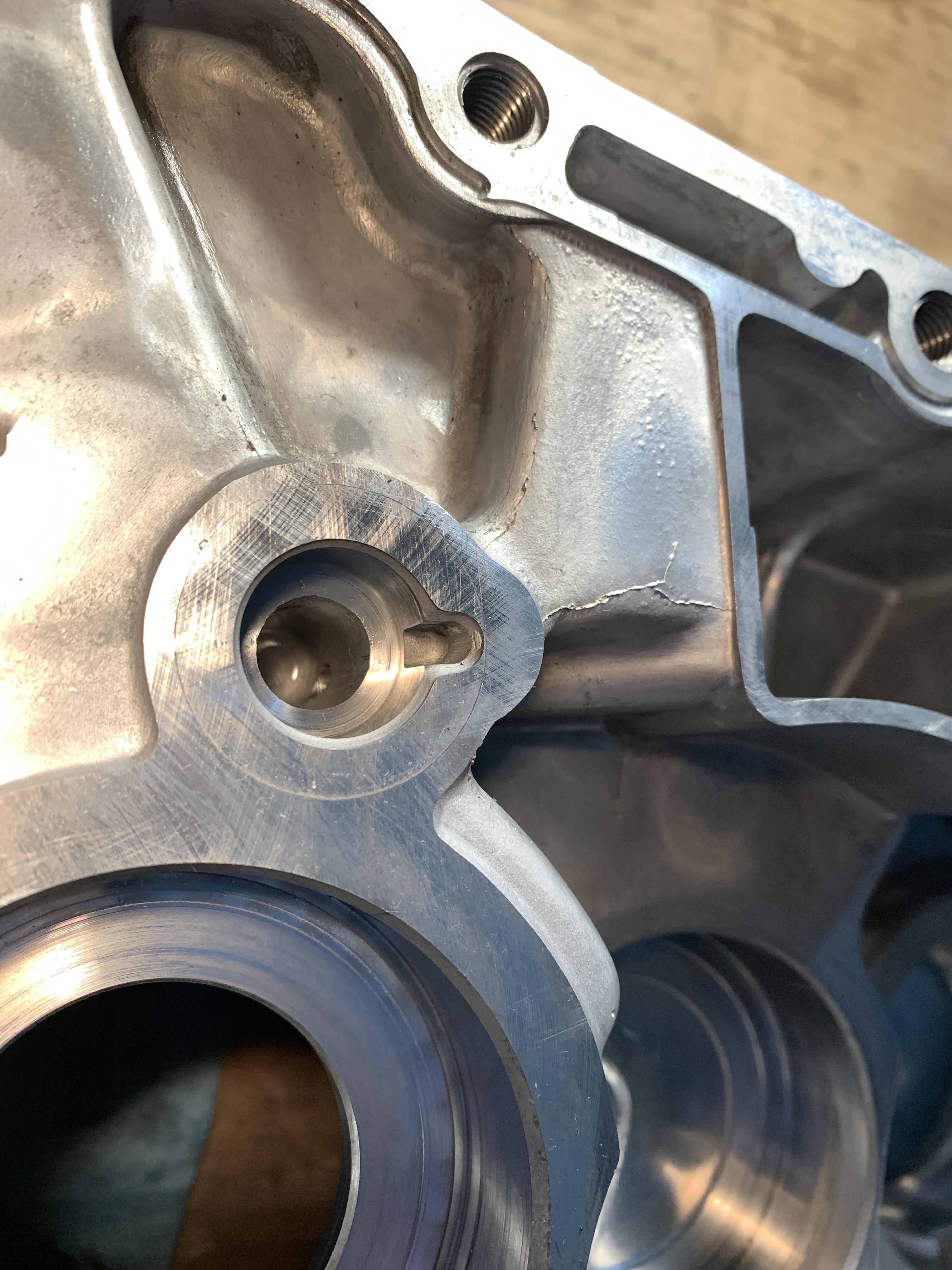
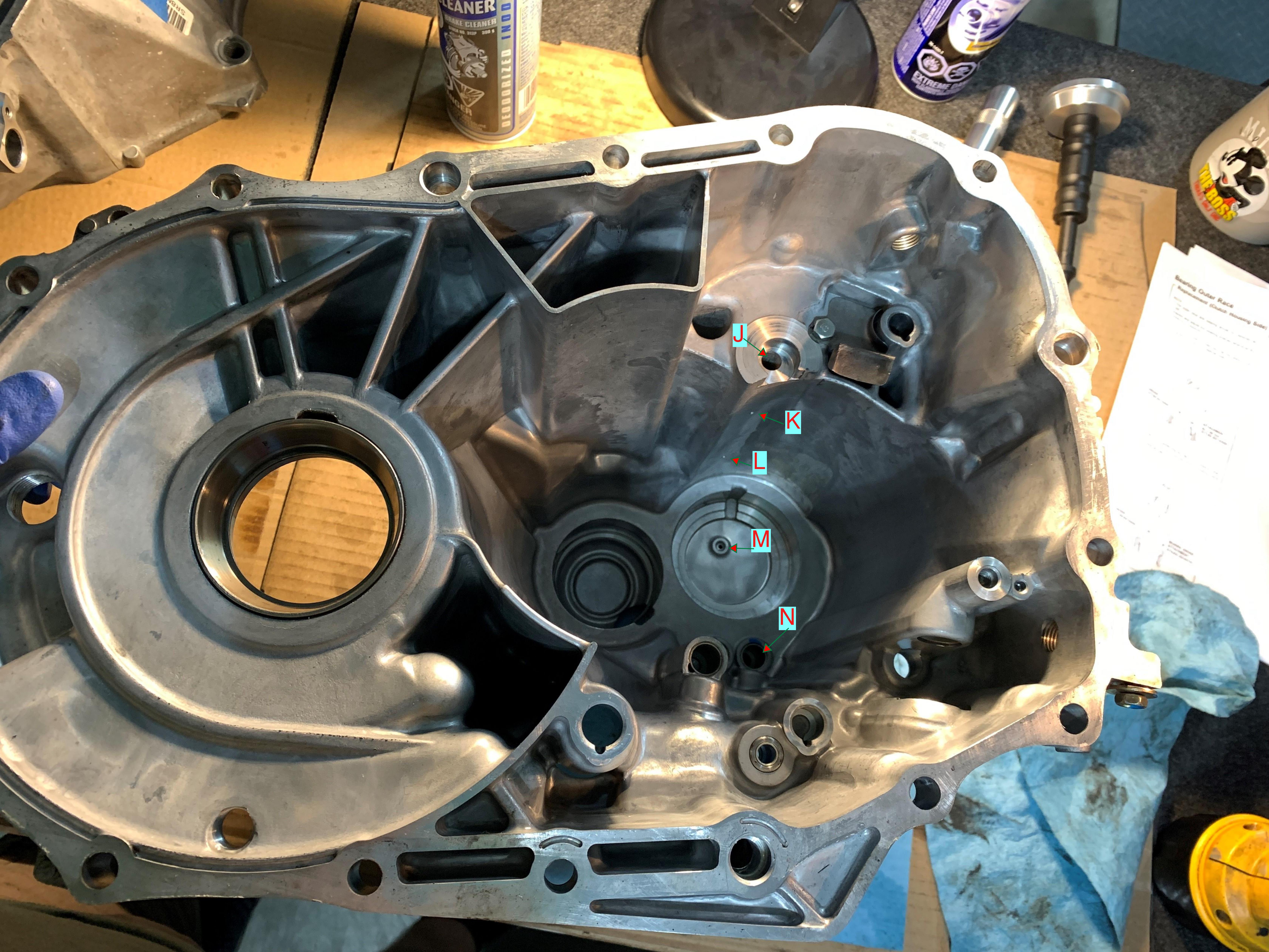
The picture below shows the clutch housing. The passages are as follows starting from the pressure source (the oil pump):

1. A to F
2. B to G
3. C to E
4. C to D
5. H to I

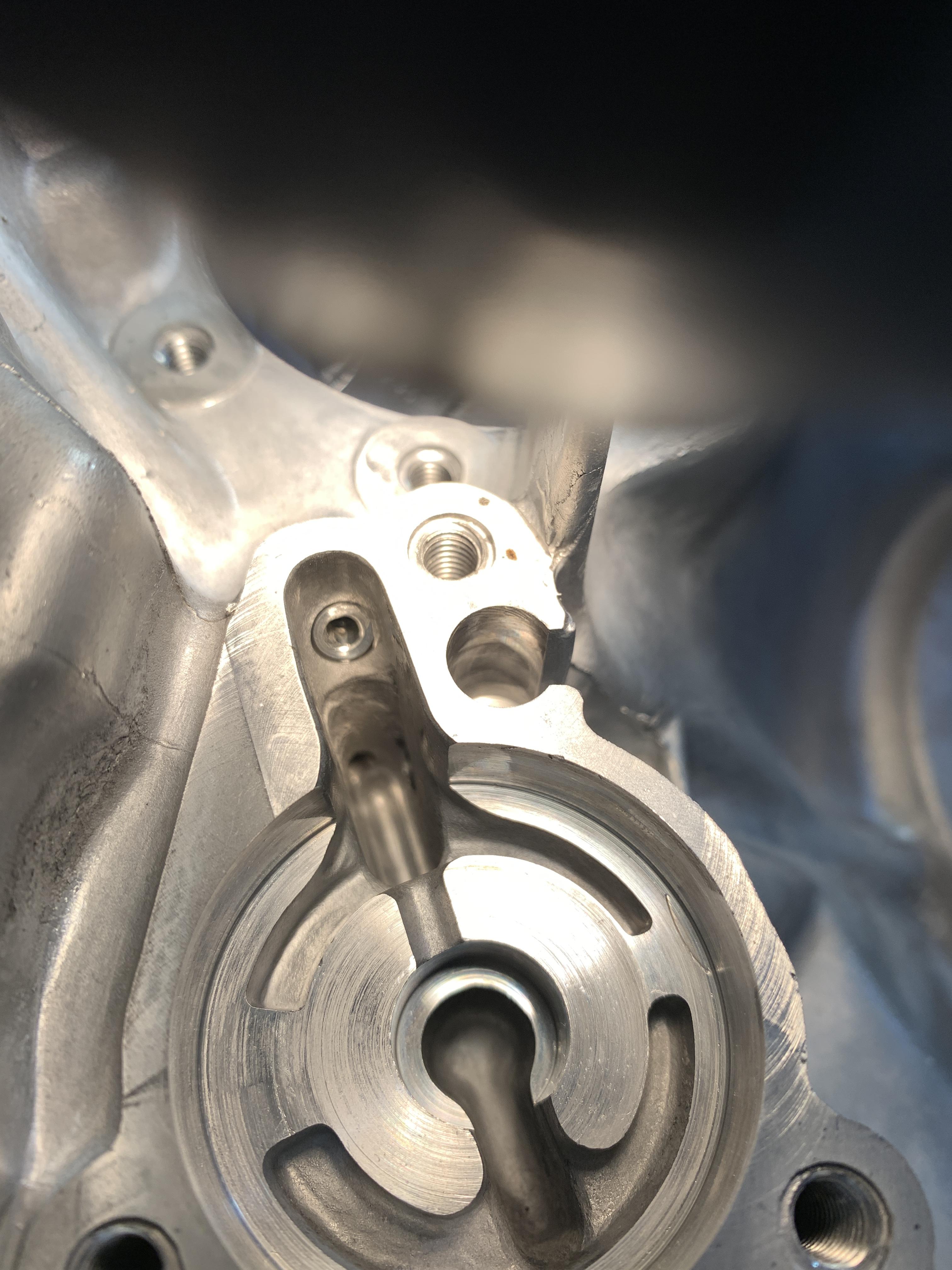
The #4 pathway from C to D is the pressure relief. If there is a blockage in the path to E then the spring and ball lift and allow the fluid to recirculate through the pump (ie because liquid incompressible yada yada yada).
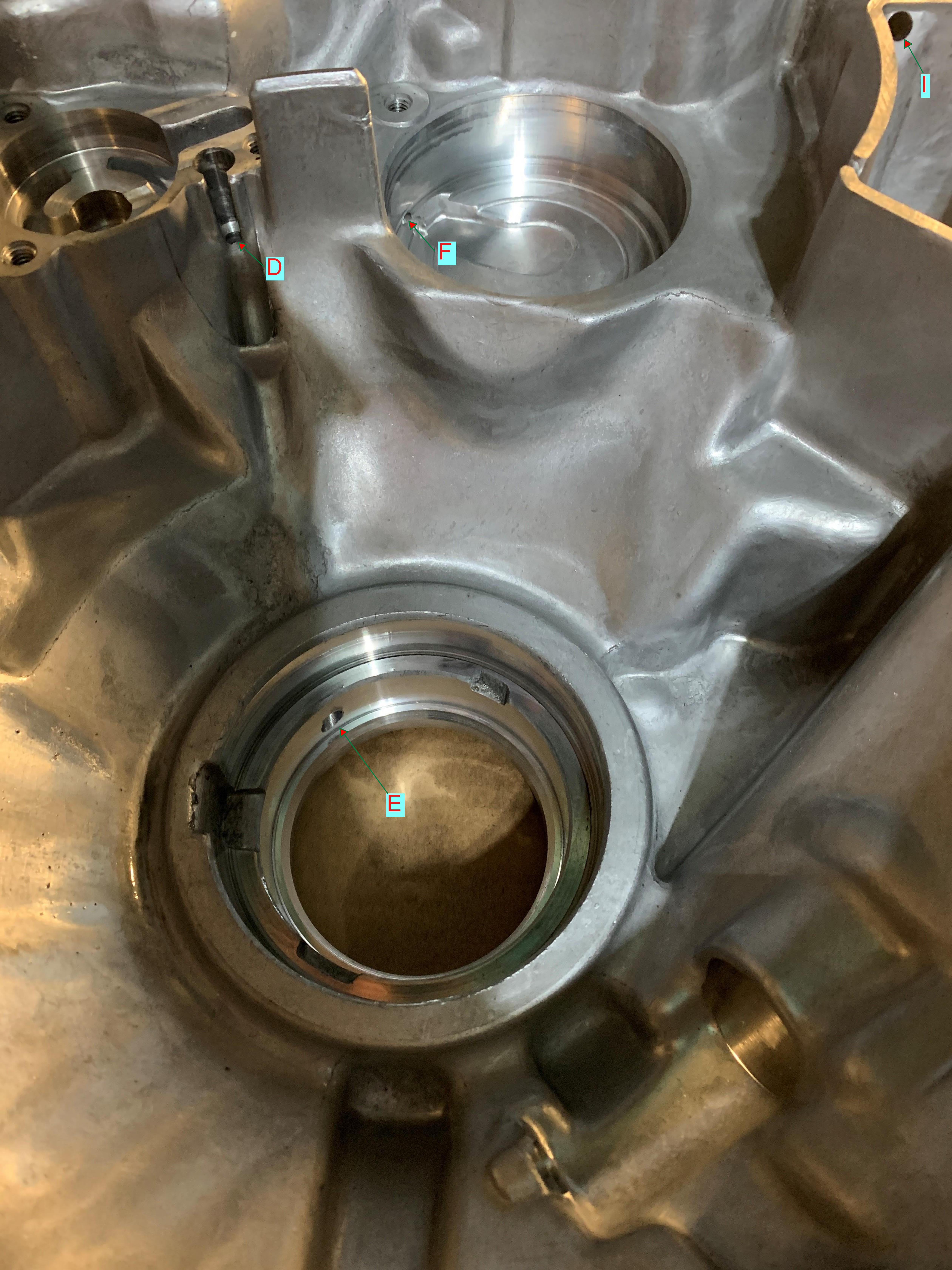
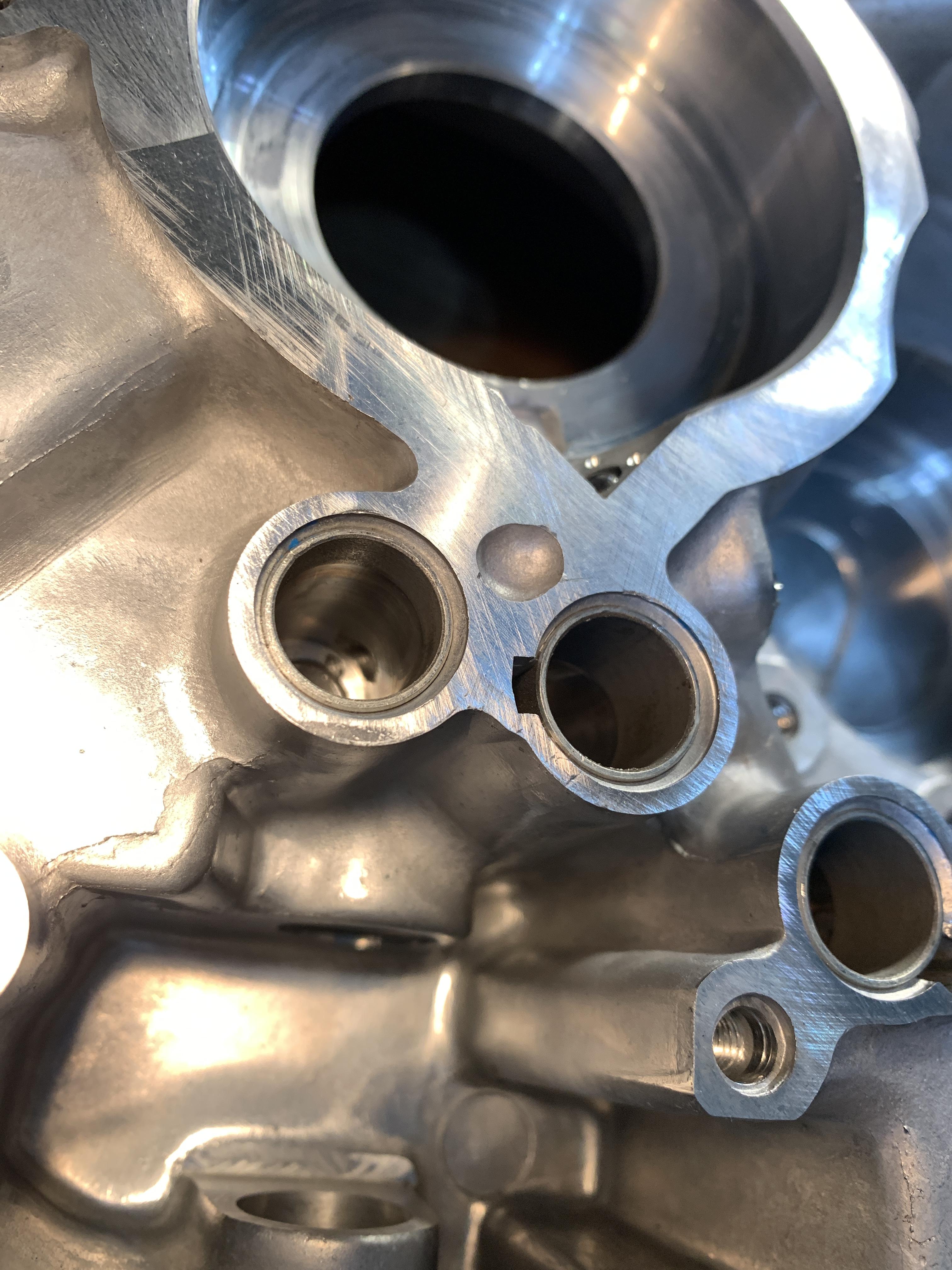
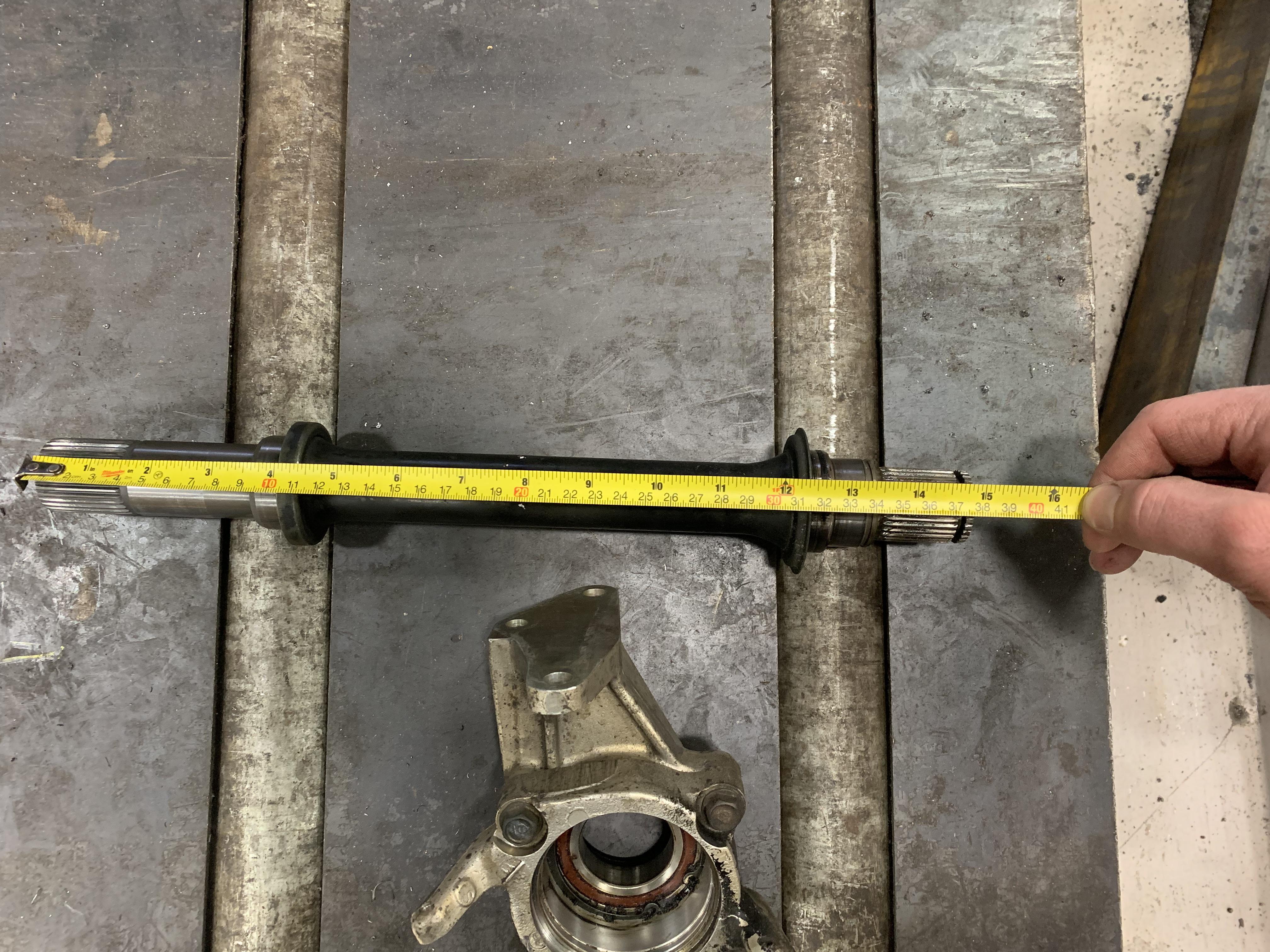
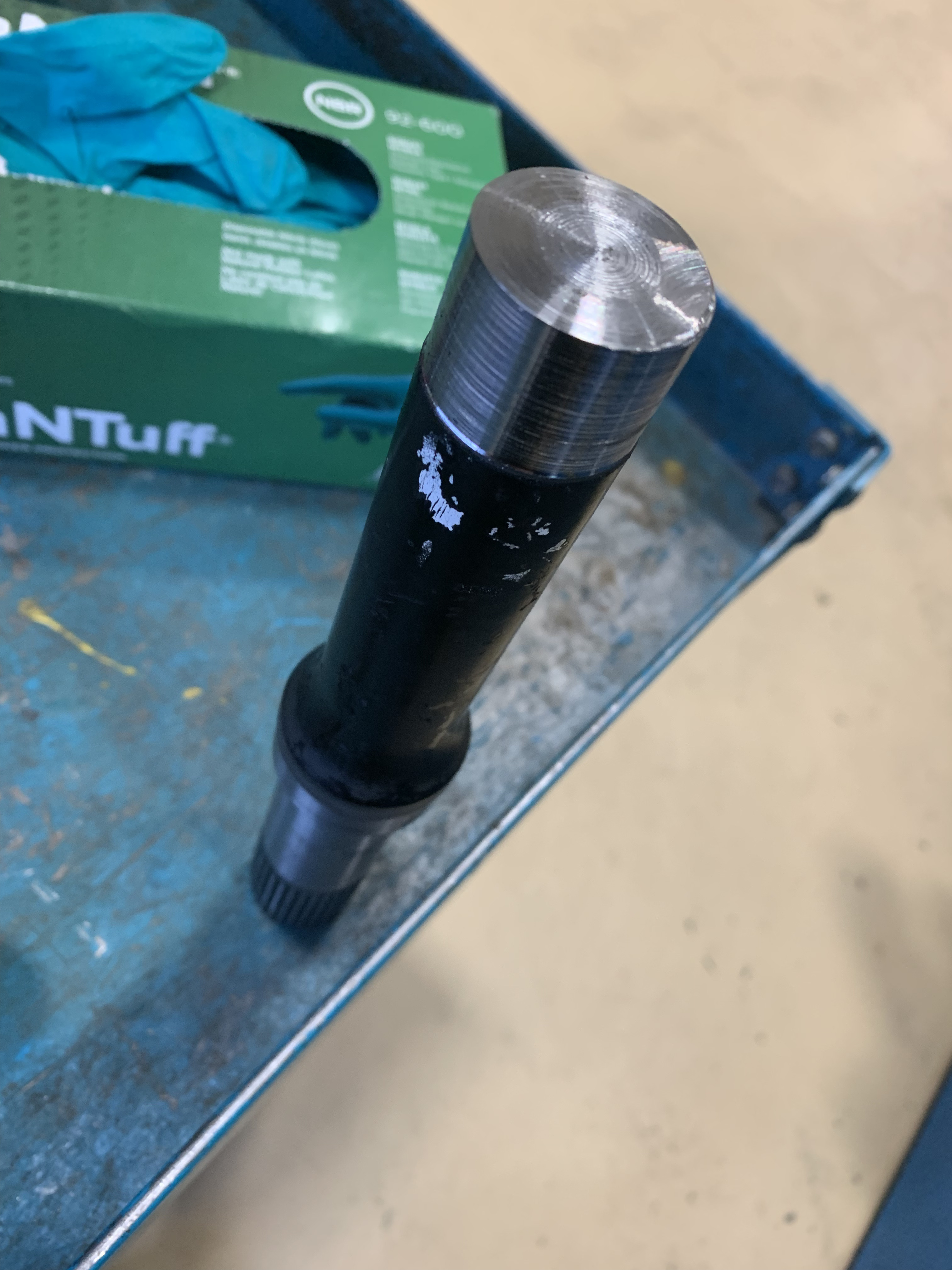
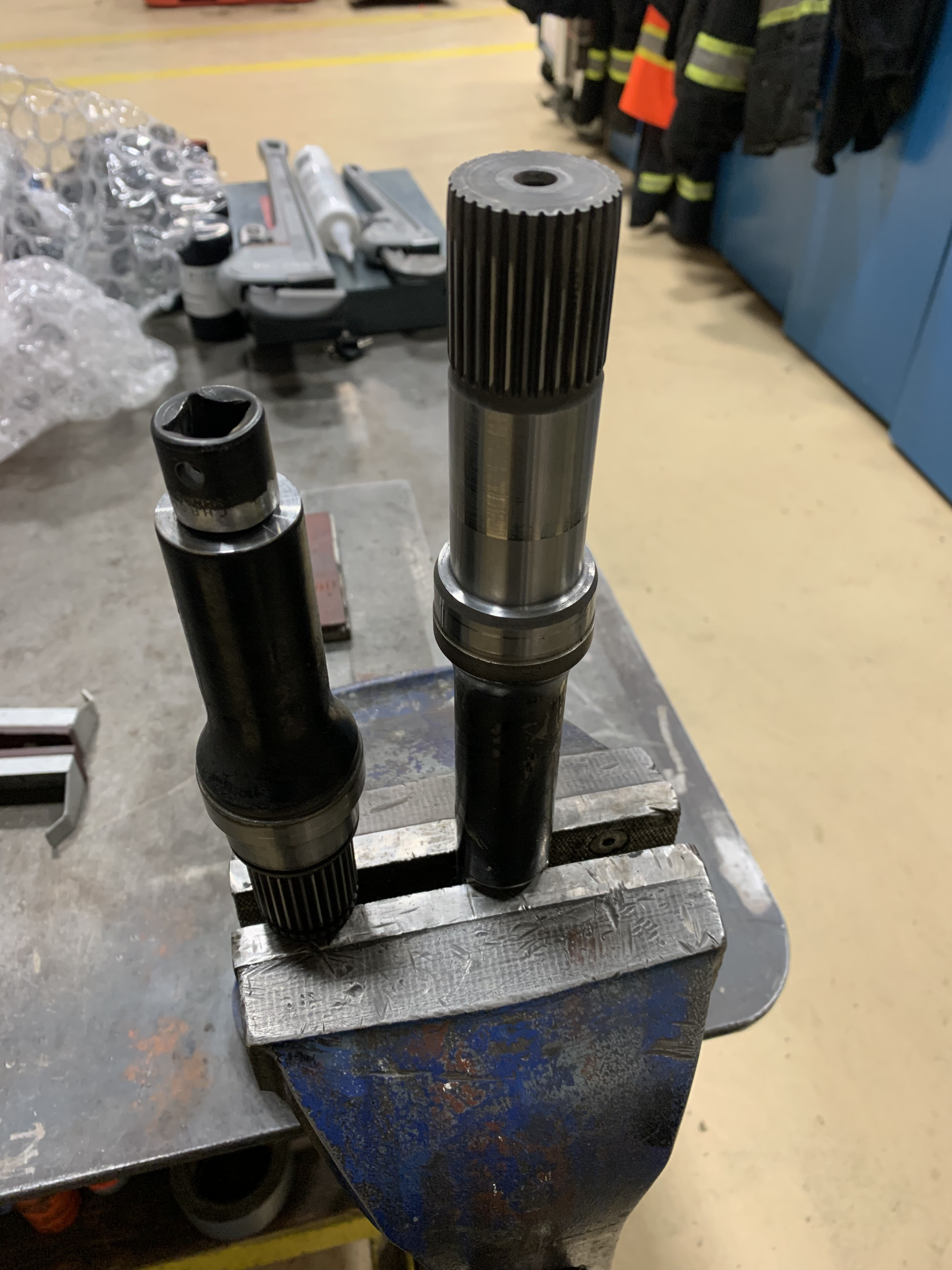
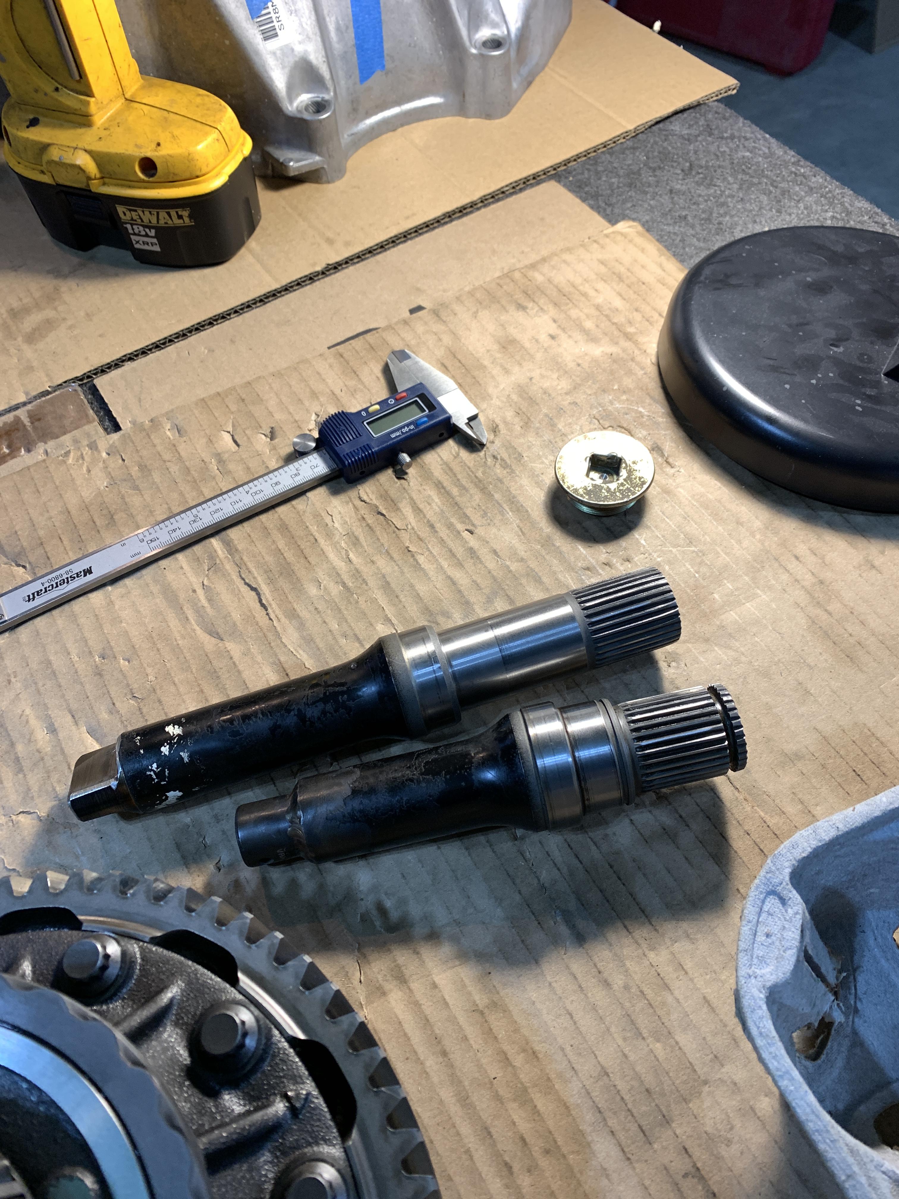
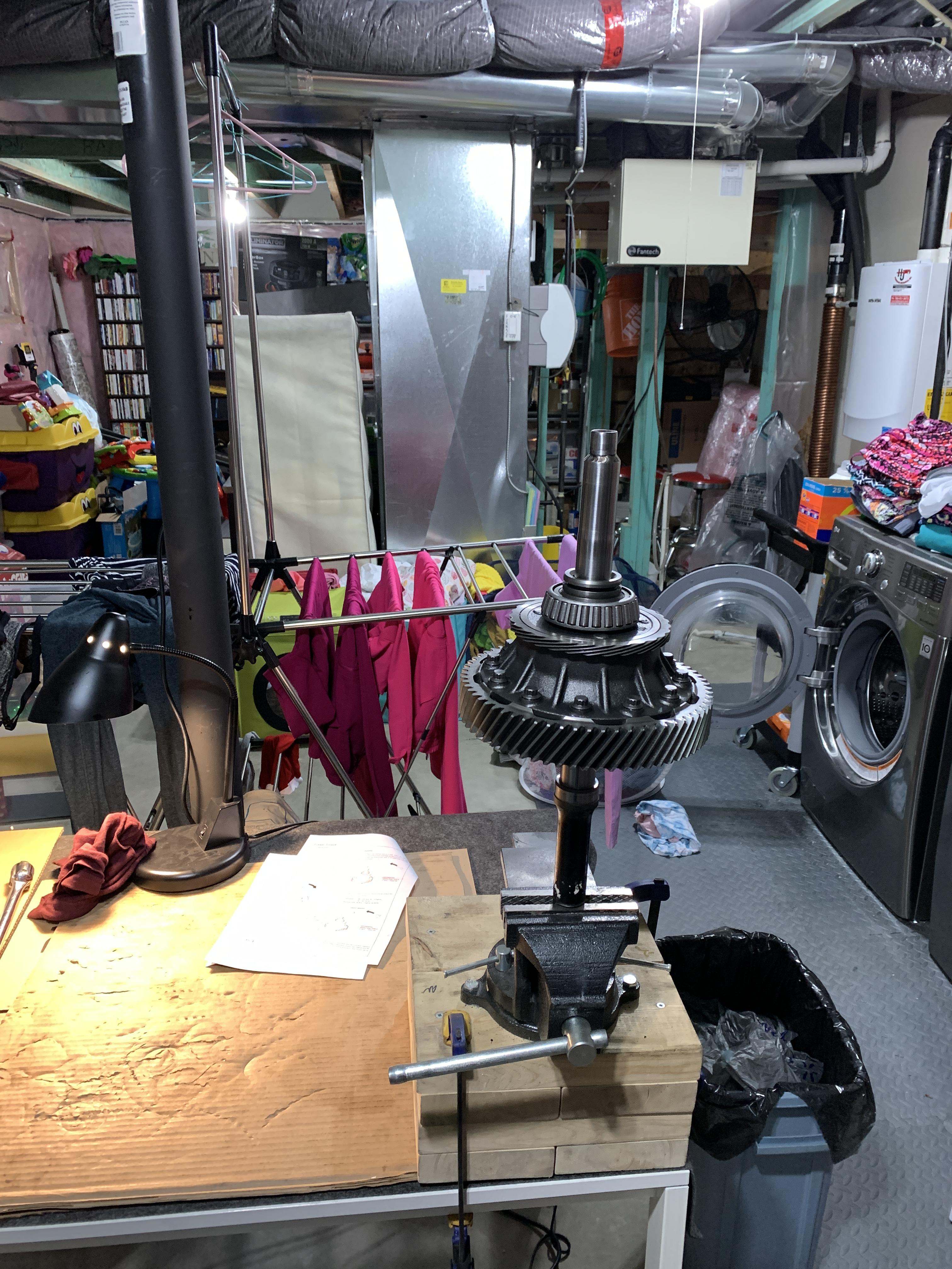
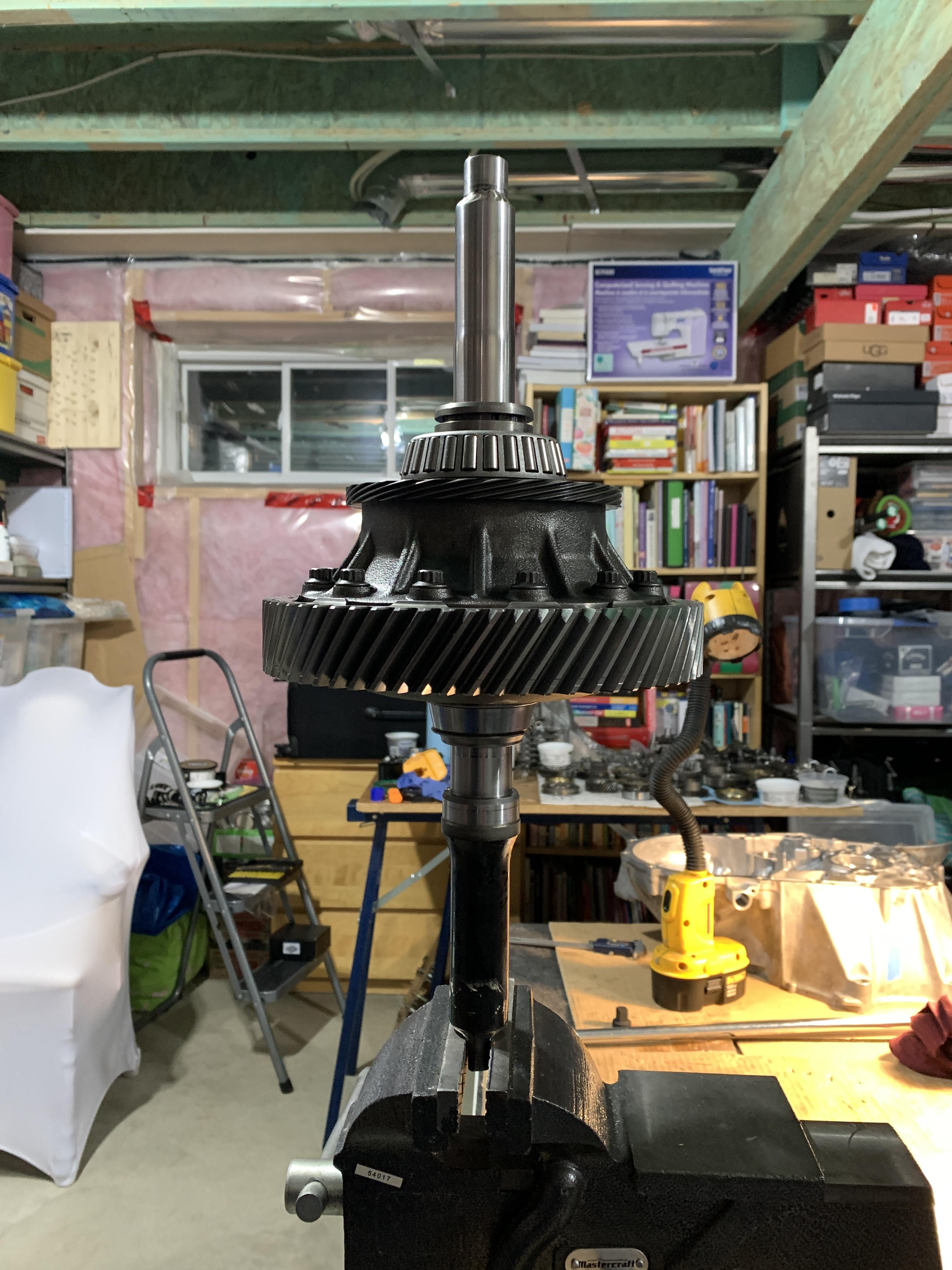
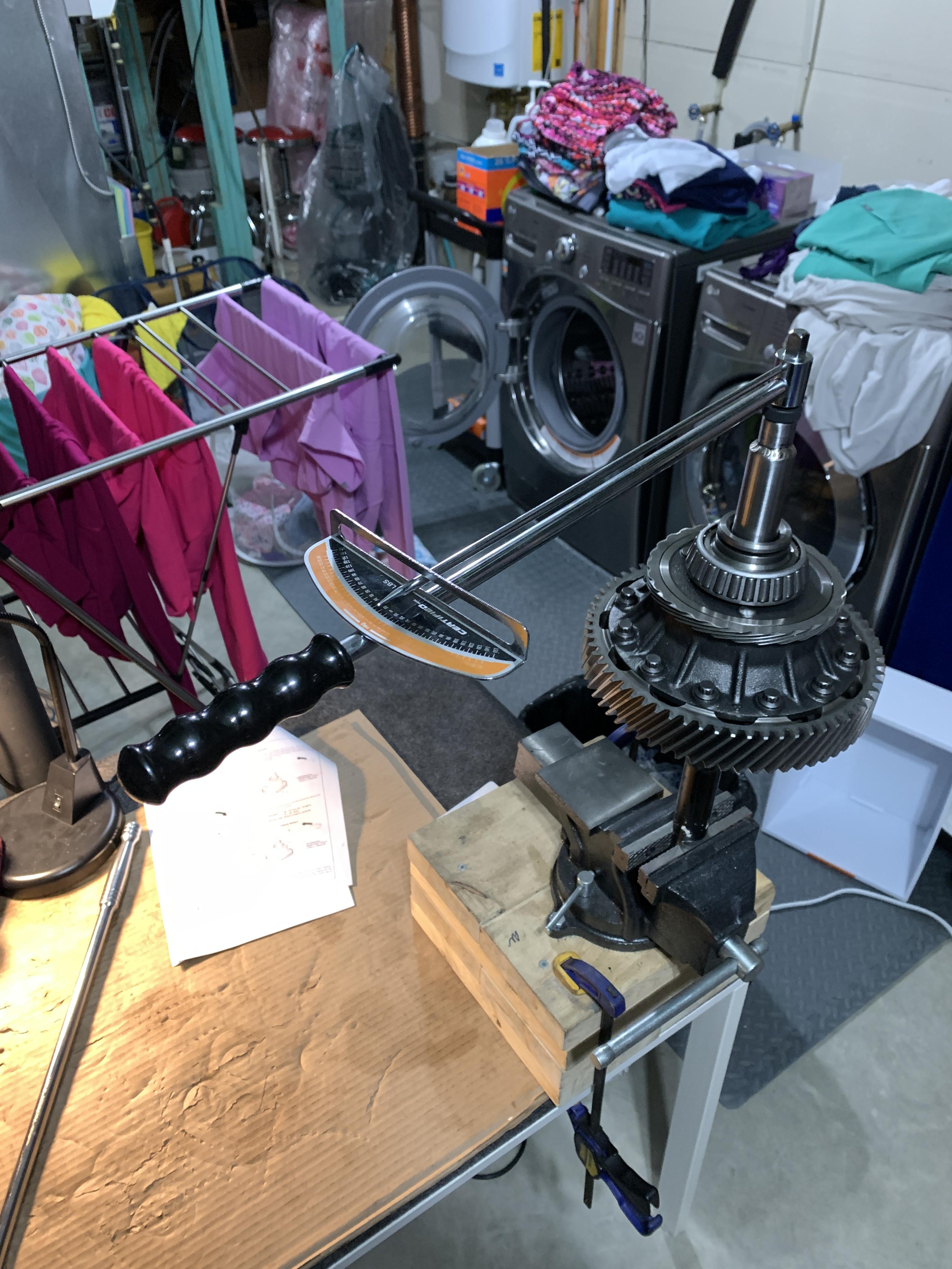
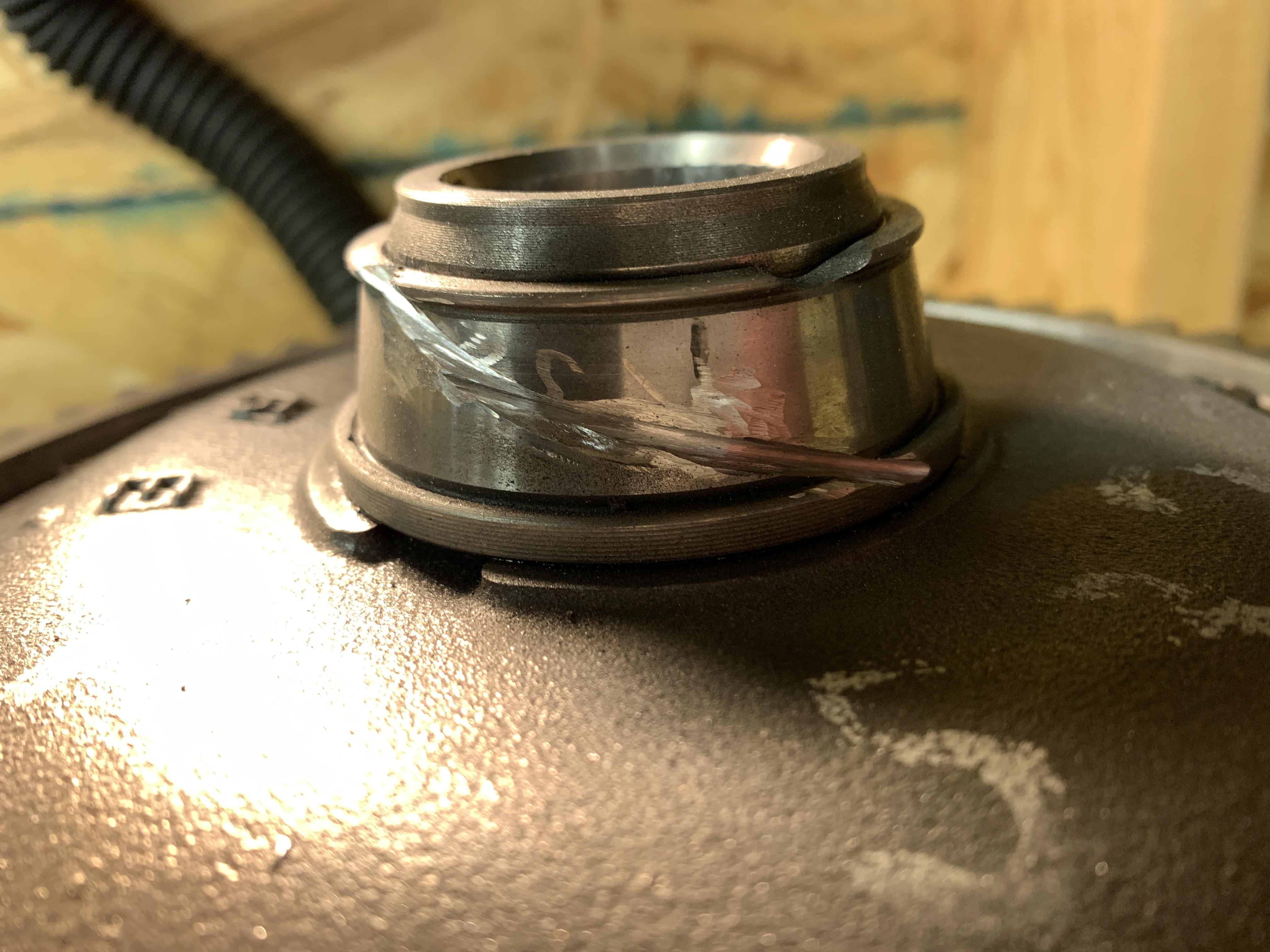
FP2sCIE.jpg
 
Here is a close up of E:
riyllFI.jpg


Another shot of E:
OM3JQ7b.jpg


Here is I:
XultIa0.jpg


Can see H in the reverse main shaft hole. This is the “3rd” primary shaft (mainshaft, countershaft, and reverse shaft). It’s just a little wee one instead of a big one.
fSXWydV.jpg


Here we can see G. This is the mainshaft shift fork shaft lubrication.
1outaQW.jpg


Here we can see F. This is the countershaft clutch side needle bearing area but I think it’s for the countershaft lubrication.
MfbQGc3.jpg


Here is a good shot of the 3 oil pump discharge passages A, B, and C:
tQIjYpZ.jpg
 
Last edited:
The transmission side is quite a bit less complicated with really only 1 main pathway. The following passages exists:

1. J to K
2. J to L
3. J to M
4. J to N

fJSK6Tb.jpg


7iJRenP.jpg


In the video my finger is blocking the J to L pathway but I can assure you fluid comes out of there.
https://youtu.be/7dc36Yfgcwo
 
Last edited:
Thank you for documenting all of this. Really nice to see a 6-speed taken down and inspected properly. I'm glad your mainshaft is ok. This trans is interesting in that the bearings are showing a lot of wear, but the synchros all look pretty good. I wonder if the magnet material was rough enough to score the bearings, but not wear the synchro teeth?
 
Fantastic thread, thank you for the very thorough documentation and pictures. This will be a great resource in the future.

As I'm following along I kind of agree with Paul. But I don't think the scoring on all those bearings is from magnet fragment metal to metal contact. If I were to make a guess, I'd say that some magnet fragments got in the oil galleys and led to oil starvation. Almost every bearing shows wear but no other items are below spec. Clean those passage ways very well.
 
Thank you for documenting all of this. Really nice to see a 6-speed taken down and inspected properly. I'm glad your mainshaft is ok. This trans is interesting in that the bearings are showing a lot of wear, but the synchros all look pretty good. I wonder if the magnet material was rough enough to score the bearings, but not wear the synchro teeth?

Fantastic thread, thank you for the very thorough documentation and pictures. This will be a great resource in the future.

As I'm following along I kind of agree with Paul. But I don't think the scoring on all those bearings is from magnet fragment metal to metal contact. If I were to make a guess, I'd say that some magnet fragments got in the oil galleys and led to oil starvation. Almost every bearing shows wear but no other items are below spec. Clean those passage ways very well.


I think you guys might be onto something. So the more I thought about it and looked everything over I'm seeing the evidence exactly how Valhalla stated it (oil starvation) and Honcho alluded to. But I remembered the Spoon magnet not being very big and with all the large pieces I found in the tranny, and the big chunks that came out with the fluid flushes, I'm starting to suspect it's not Spoon's fault. I actually found the exact "before" picture of the Spoon plug. Notice its size is quite small.

aIDOUqf.jpg


...and where it broke off:
Z6z5Ugy.jpg


So then I thought where else can magnetic bits come from and then it hit me.....I think the factory Honda magnet let go on me! I mentioned earlier it was weird how the magnet carrier has spots for 2 but only has 1 magnet installed. I suspect it's SUPPOSED to have 2. This would explain the sheer volume of bits I'm finding.

Can someone confirm if the factory magnet is supposed to have 1 or 2 squares....because mine suspiciously looks like it's missing one of them. If that's the case then this is factory component failure that caused this mayhem! I'm guessing the big bits of factory magnet hit and sheered off the Spoon one. I wonder if I can warranty a 16 year old transmission???? They'd probably blame aftermarket Spoon parts and deny claim anyways haha.


EfnJ638.jpg


q5ZFKrX.jpg
 
Fantastic thread, thank you for the very thorough documentation and pictures. This will be a great resource in the future.

snip snip

Clean those passage ways very well.


Solid advice as yourself and the others have mentioned about the passages. I took a very poorly framed and sideways video showing all paths are cleared. I did the tranny side in my earlier post. Once my compressor isn't frozen anymore I'll blast the passages with air too just to make sure.

I went easy on the brake clean in the video but off camera when I gave it a hard squirt the brake cleaner nearly hit the ceiling.

https://youtu.be/zbzY3YQRiCY
 
Now I moved onto to the outer race on the transmission case side. The service manual says to heat up the case or to pry out the race. I speculate this is because if you try to punch it out then the case could crack as the race is right on a high point of the case (?weak spot?). Having said that I see a bunch of people just punch it out which is exactly what I was planning to do too but then figured what the hell, if service manual says to do it then I’ll give it a go.

For the record a 2.470 inch race driver is the perfect fit.
KxWKrhI.jpg


https://youtu.be/EPub1-bxp-M


Here was my setup. I have just a standard issue heat gun and a cheap laser thermometer. Note that the race driver handle is supposed to be the silver one (and not the black) for hammering.

Q0yFQC2.jpg


I began heating up the race area from the outside. Just using circular motion and not staying in one spot for long. I checked the temperature “live” every few seconds and temperature rise was gradual. Once I got to what I estimate ~160-170 degF the race simply fell out. By that I mean I saw it wobble a tiny bit so I just pushed on it with my finger and it came down! I assume this is why the service manual says to heat the case up as it was very easy to do.

I tried to grab a picture of the case at hot temperature but by the time I did it was already cooled down to 111 degF ish. Either way great success.

JD2mhJz.jpg


dr252N9.jpg


My shim measured in at 2.13-2.14 mm. I took the lower value closer to 2.12 mm.

MefXozp.jpg


U0veX7p.jpg


With this outer race done this now completes the full disassembly of the case housings. It’s only putting it back together from here on in. I already cleaned all the goo off the mating surfaces so once I get the parts I’ll just do a quick acetone and be good to go.
 
Last edited:
I briefly moved onto the differential carrier bearing inner races but failed to get them off with the pullers I had. I did try though. It just ended up breaking the inner race (which was expected). The proper tools are hundreds of dollars so I think I’ll just have to take my time and cut the inner races off with a Dremel. It’s not the “wrong” way to do it but shops wouldn’t simply due to the time it takes. If they have the proper tools (and they should) then it’s a 1 minute activity.

Here is the proper tools:
ZzAhsx1.jpg


Here is my setup which failed:

DuuYmNK.jpg


ZWM46i0.jpg


Wear eye protection! That little piece went flying somewhere and I still haven’t found it.

3cxbJcM.jpg


sTvDvro.jpg


I don’t know what kind of puller would be thin enough to fit into that slot and strong enough to take the race off.

IHpdlSx.jpg
 
After that my wife came in and said her Subaru feels funny on the ice after hitting a big hole. So instead of showing you my Dremel skills I’ll leave off with a few pictures of a poo brown Subaru and some NSX under the cover. Somehow the Subaru bushings got torn to bits and holy crap is this thing sketchy to drive. I’ll need to sort this out asap so the inner race will have to wait a weekend or 2.

c24k2Hq.jpg


pXcF5Hn.jpg


NIYiQVt.jpg


I guess they don’t paint where the sun don’t shine under the engine cradle beams.
8IWXMiq.jpg


Very briefly several bushings failed so hard I can “clank clank” the control arm against its mounting just by hand.
OJiSEow.jpg


Bad bushing:
qL3vMTG.jpg


Bad bushing:
rjHklL7.jpg


Reference a good bushing on the other side (good meaning 275k kms):
ogrOPLw.jpg
 
Last edited:
For the NSX I’ve basically accomplished all I wanted to do over the Christmas break as I knew I’d be waiting for the differential tools. Hopefully I’ll have those by the end of January. This thread will go quiet for a bit but I’ll pick it up again once I take the diff apart and then once again when I finally get the parts in (estimating End of March).

If you've kept up to date so far even with the metric shit tonne of pictures then good work!
 
Huh. My trans only had 1 magnet, but it had been taken apart before I got my hands on it I suppose. But, I can't see why the rebuilder (i.e. Cody) would purposely pry one of two magnets out and leave it like that. I also don't see any mechanism for the OEM magnet to disintegrate by itself, the end of the Spoon magnet is a different case. I feel like I've seen some pics with just one magnet in the holder as well but I can't find them. Maybe another P/N variance?

I tried the same bearing puller setup as you for the diff taper bearing removal. I was fortunate enough to get the entire bearing off, but the outer cage was mangled like yours in the end (but didn't break free from the inner race). I ended up grinding the edges of the puller plates(?) to a sharper edge in order to bite into the gap below the bearing more after it slipped off a bunch. Slow process of walking the bearing up but I'm sure heat (i.e. butane/MAP gas) would help a lot. See abomination of improper tools below.
L5NGKnU.jpg
 
Huh. My trans only had 1 magnet, but it had been taken apart before I got my hands on it I suppose. But, I can't see why the rebuilder (i.e. Cody) would purposely pry one of two magnets out and leave it like that. I also don't see any mechanism for the OEM magnet to disintegrate by itself, the end of the Spoon magnet is a different case. I feel like I've seen some pics with just one magnet in the holder as well but I can't find them. Maybe another P/N variance?

I tried the same bearing puller setup as you for the diff taper bearing removal. I was fortunate enough to get the entire bearing off, but the outer cage was mangled like yours in the end (but didn't break free from the inner race). I ended up grinding the edges of the puller plates(?) to a sharper edge in order to bite into the gap below the bearing more after it slipped off a bunch. Slow process of walking the bearing up but I'm sure heat (i.e. butane/MAP gas) would help a lot. See abomination of improper tools below.

Haha, love that setup and especially the c-clamp! You took it one step farther than I did and glad it worked out.
 
It should have two magnets. :)

Huh. My trans only had 1 magnet, but it had been taken apart before I got my hands on it I suppose. But, I can't see why the rebuilder (i.e. Cody) would purposely pry one of two magnets out and leave it like that. I also don't see any mechanism for the OEM magnet to disintegrate by itself, the end of the Spoon magnet is a different case. I feel like I've seen some pics with just one magnet in the holder as well but I can't find them. Maybe another P/N variance?

The Spoon magnet looked to be much stronger material so maybe that's what blocked my oil passages? I wonder how many OEM magnets let go so far and people just don't know about it (and how would they really know). I might switch my tranny fluid changes to be more frequent just in case the new one lets go too. Or maybe put some Hondabond around the edges of the new magnet to keep it in place.
 
I have 2 corrections I need to make. That’s sometimes the good part about leaving something alone for a while especially if you’ve never done it before.

Correction #1 : the 2.13-2.14 mm carrier bearing shim I measured before is in fact correct….I was just using the wrong table. It’s now corrected in the post.

MmwHoUV.jpg


x1k3PqI.jpg


Correction #2 : I was looking at the case and it suddenly clicked to me that the 3rd oil passage through the tranny isn’t for the reverse shift fork…it’s for the reverse main shaft itself. There are 3 primary shafts in the transmission:

-Mainshaft
-Countershaft
-Reverse shaft (although it’s a little wee one)

That lubrication is 100% for the shaft/gears and not the fork so that makes more sense now.
 
Back to the tear down. My buddy came through with the tools but they’re still a work in progress. The tool side is pretty much done but the vice/holder side is going to get re-worked. The guy who operates the lathe was on extended vacation so my buddy left the holder long and just used an angle grinder to make the “flats”. We’ll shorten it up in due time.

First step is to press out the shaft out of the IMS bearing. Here is the length (automatic transmission IMS):
dzmAL3m.jpg


Z5Gy6dZ.jpg


..and then proceed to cut it in half (kind of). We left the vice side longer since we knew we were going to come back to it.
vrHcYuB.jpg


My buddy said the shaft material was extremely tough and chewed up his bits. Not sure what this IMS is made of but it’s high quality; even from a 1991 automatic. In some spots it was dual layer which doesn’t make any sense at all. How would you even manufacture that…

n07apeM.jpg


MIHbpiO.jpg
 
He had an old broken impact extension laying around so that is a perfect fit for what we’re trying to do.
S5TA18b.jpg


First is to clean up the bit a bit:
MYYrwLQ.jpg


Then make a recess in the shaft:
Z3EVBCy.jpg


Fits nice:
kAjzGxl.jpg


Now the vice/holder side. Marked out how deep the “flats” should be:
4CmuvtT.jpg


Then angle grinder it off:
9joOV7W.jpg
 
Tried to round it off to beautify it a little bit but ended up not being as nice. And kind of a detriment since it can “roll” out of the vice. We’ll cut this part off in the next few months but it’ll work for now (checking the breakaway torque to see if I need to buy new clutches).
6JqOjrV.jpg


SuLVkrK.jpg


And here is some freshly made tools (pre welding that one side):
pxyLGB5.jpg


Then weld it up and call it good:
Zvr6DPf.jpg


Then my buddy came over and we were going to check the breakaway torque…..until we realized what we overlooked:
2X60AcB.jpg


The side that has the actual IMS bearing on it won’t fit in the diff deep enough to engage the splines. Dang it!!!! Never even thought of it but it was also obscured by the IMS bearing carrier too so we weren’t too hard on ourselves.
VOnm51T.jpg


Back to the lathe and ground down the tool side flat. Again, just getting this amount of IMS material off chewed up 2 bits so super strong material. They were old bits but none the less.

PiweVb9.jpg
 
After a week, got the tools back and got going on it again properly. Some parts are slowly starting to trickle in too:

HPYDMr1.jpg


hVa1z3g.jpg


On the diff side I could finally hold both sides. The tool side isn’t fully engaged in the following picture as both sides are sitting on their splines.
nSBTTg0.jpg


jhWaqtj.jpg
 
Then proceeded to check the breakaway torque. The standard values are between 43-101 ft-lbs; mine came in bang on 50 ft-lbs. It’s on the softer side but is that really a bad thing? Yes for racing but for comfort 50 ft-lbs is perfectly fine as I won’t drag the inside wheel in parking lots. I’m just happy the clutches don’t need replacing as that’s a boat load of money.

5hMyV8d.jpg


I had my wife stand on a ladder and take as best of a top down view as she could get. It’s the most accurate towards the end of the video since she wasn’t reaching over the table. Before I took this reading I spun the diff 5 full turns in the “breakaway” set up as the service manual calls out to do (using a breaker bar and not the torque bar). All I can say is I’m out of shape haha …..

https://youtu.be/LnqpTULT_54

Now with breakaway torque known and the temperature outside at a “tee shirt and shorts” 0 (zero) degrees Celsius I can begin with getting the inner carrier bearing races off. The wife politely advised (aka demanded) I don’t get metal shavings in the basement.
 
I went and bought a couple of these cut off disks for the Dremel and honestly I barely used up a quarter of one of them. Definitely worth the money.

vUPFbYN.jpg


1lzEw48.jpg


You will also need some chisels
G0HNtkB.jpg


Grab your fancy new tool and get your setup setup:
iSIILYd.jpg


UOBAfUH.jpg


And now slowly start using the Dremel to get the inner race material off. I had to do a long spiral as if I went straight on then the disk would hit the diff cover.

gfEbpQr.jpg


ElH2o41.jpg


CzldE7L.jpg


X0xD5Tk.jpg
 
Back
Top