• Protip: Profile posts are public! Use Conversations to message other members privately. Everyone can see the content of a profile post.

Climate Control Unit (CCU) repaired

Joined
12 July 2009
Messages
220
Location
Maryland
So I just purchased an NSX last Friday and the CCU died the day I purchased the vehicle. The CCU worked a week ago when I test drove it, but the day I drove it home I got the "fan stayed on & no CCU".

I pulled out the CCU and sure enough 3 capacitors exploded and some traces messed up. I removed the bad caps and cleaned up the board and did some soldering. I won't say too much since I know BrianK does majority of these fixes. I will however leave you with pics of my experience.

So anyways as much as some of you would be upset for something like this happening, I quite enjoyed it as my job is problem management and I like to fix things and how awesome I already got to work on my NSX and fixed it for free.

Enjoy the pics.
 

Attachments

  • P1010072_l.jpg
    P1010072_l.jpg
    93.7 KB · Views: 902
  • P1010073_l.jpg
    P1010073_l.jpg
    98.8 KB · Views: 791
  • P1010077_m.jpg
    P1010077_m.jpg
    93.4 KB · Views: 723
  • P1010078_m.jpg
    P1010078_m.jpg
    99.6 KB · Views: 723
  • P1010080_m.jpg
    P1010080_m.jpg
    92.7 KB · Views: 698
  • P1010082_l.jpg
    P1010082_l.jpg
    96.6 KB · Views: 663
  • P1010083_l.jpg
    P1010083_l.jpg
    101.8 KB · Views: 644
  • P1010084_l.jpg
    P1010084_l.jpg
    101.6 KB · Views: 651
Last edited:
I too wish I had the knowledge for tasks such as this.
Looks like you have a nice little collection of capacitors and as such there.
I understand about the feeling of accomplishment of fixing something yourself.
Great job.
 
Nice job! Looks like an easy fix. If mine goes I'll know which parts to look at replacing right off the bat. Thanks!
 
very nice job, thats very delicate rewiring you did, are you getting any "clicking sounds" when you cycle through various vent settings? (feedback loop issue). Your fan speed control should probably work fine now (based on your pics) but I'm not sure if you corrected the feedback loop issue. Okay great work!
 
I like to watch DIY.

For future DIY'ers please remind: Changing out the caps is only half of the job. A pro does the second part also. :) The most difficult thing with the traces is that you can't see them anymore after being eaten up by the caps. If you do it the first time on a badly eaten up board you better have a reference board to see where the traces route. :wink:

BTW: why did you only change the leaking caps? The other ones will start leaking soon too...
 
Last edited:
I like to watch DIY.

For future DIY'ers please remind: Changing out the caps is only half of the job. A pro does the second part also. :) The most difficult thing with the traces is that you can't see them anymore after being eaten up by the caps. If you do it the first time on a badly eaten up board you better have a reference board to see where the traces route. :wink:

BTW: why did you only change the leaking caps? The other ones will start leaking soon too...
Because I only had 85C rated caps at the time I pulled it apart. I didn't want to have to change everything twice. I will replace all with better ones later. I have to Drive to Pittsburgh for the Vintage Grand Prix tomorrow morning so it was more of a quick fix for now.
 
I changed the coolant on my car 2 weeks ago, including the step of setting the temp at 90F so the heater core fully drains. During the process, my CCU failed - the blower stuck on high speed.

I had the CCU apart in Oct 2008 and found no signs of any capacitors failing. The CCU also passed the self-test procedure last summer when I was investigating inadequate cooling (that turned out to be a cable needed adjustment).

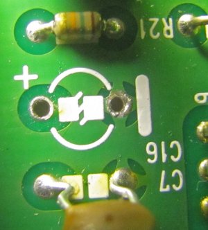
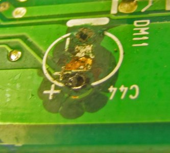
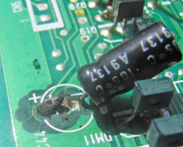
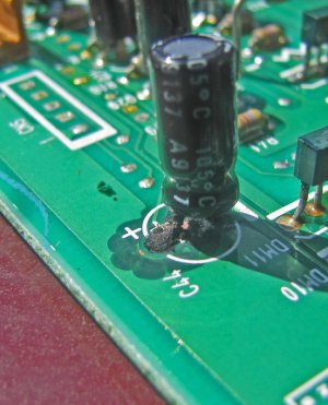
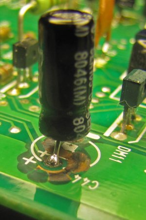
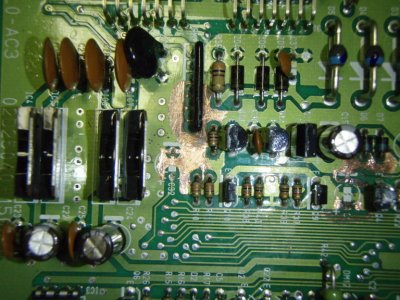
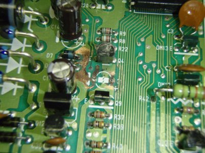
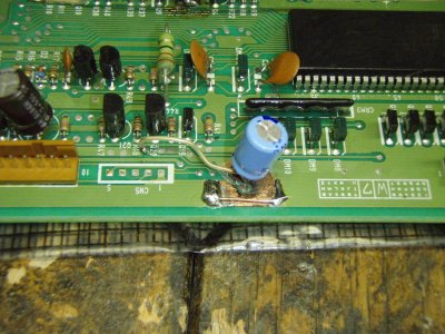
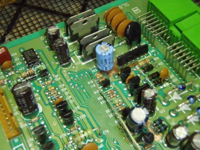
I'm suspicious that the root cause is a circuit design problem. The capacitors that failed in Nick675's CCU were C44, C11, and C32. On my unit, it was C44 and C11. I was lucky to catch C11 before it did any damage to the printed wiring board. C44 created a somewhat ugly mess, but all the paths are still intact. The attached pictures show C44 before and after cleanup & a new capacitor install, as well as a cleaned area under a good capacitor (C16) to show just how much damage was done by C44.

In other posts on Prime, I have seen C44 and C32 clearly idenitfied. So, there is a trend involving these 3 specific capacitors.

From a simple visual inspection of my two capacitors, this looks more like a "blowout" than a slow leak. I'm retired now and no longer have access to a component failure analysis lab and the usual assembly "goodies" in the lab. I cleaned up the board first with isopropyl alcohol (rubbing alcohol), then with some tuner/circuit board cleaner. With the rubbing alcohol, I applied some with a Q-tip, let it soak a minute, then went back and "scrubbed" the area using a Q-tip soaked in more alcohol. A soft wooden toothpick also is a good tool in that it cleans the crud but doesn't damage the board.

I'll to come up with something to seal the exposed copper under C44. I have a temporary work stop in that I missed ordering one capacitor value. I'll give an update when I do the final install & test.

I remember a number of ways to quickly destroy electrolytic capacitors, including:
1. Too high an inrush current
2. Reverse polarity (not from installation, but during circuit operation)
3. Exceed the voltage rating.

Does anyone have even partial schematics of the CCU - especially in the areas involving C44, C11 and C32? There is no detail in the ETM (Electrical Troubleshooting Manual), just a box labeled "Automatic Climate Control Unit. With a schematic I might be able to determine the root cause of the capacitor failures and design simple work-arounds. One could argue the life rating of the capacitors is only 2000 hours, but the fact that failures are most prevalent in these 3 capacitors, and most "violent" in C44, suggests its not that simple. Besides, I've never heard of any failures in the same type electrolytics in the other CCU board. I've also never had an electrolytic capacitor fail in any of the electonics on my 3 other cars, all of which have more miles than the NSX, are not babied as much, and only one car is younger.

Just in case its a capacitor design defect, I've used Panasonic and CDE instead of Nichicon for the replacements. We'll see if they last for at least another 14 years.:biggrin:
 

Attachments

  • C16 area cleaned.jpg
    C16 area cleaned.jpg
    85.4 KB · Views: 293
  • C44 area cleaned V2.jpg
    C44 area cleaned V2.jpg
    72.7 KB · Views: 321
  • C44 tilted.jpg
    C44 tilted.jpg
    98 KB · Views: 339
  • C44.jpg
    C44.jpg
    89.2 KB · Views: 312
  • New C44 installed.jpg
    New C44 installed.jpg
    67.3 KB · Views: 321
Blower stuck on high speed is normally not a CCU issue unless the unit is dark.

You may what to ohm out the trace by C44 it may look OK but .....

C44 is filtering a chopped DC signal so it take a beating and fails.

C32 is getting cooked by the driver IC's it is next to.

All the rest are just poor quality caps.

You realy don't need to re-seal the copper, the orginal coating (solder mask) is so the board can be wave soldered and the solder only goes where needed.

There are no schematics available that I know of.
 
BrianK,

Thanks for the reply.

The unit was not dark, so maybe the blower wasn't really stuck or I have another issue.:frown: In any case, it made me look at the CCU so that I caught the C44 issue somewhat early.

I used a DMM and checked out the trace to C44 after clean-up and again after soldering in the new capacitor - it looks OK (< 0.1 Ohms).

For C32, I made sure the drivers were as vertical as possible and leaned the new capacitor a little away from them to try to reduce any localized heating.

With C44 used to filter a chopped DC signal, two tweaks might be possible, but they are SWAGs without knowing the actual circuitry. One is to put a very small series resistance (1 to 10 Ohms) in the capacitor lead. That will limit in-rush current, but I don't know if the circuit will still function properly - ie, the ripple voltage will increase slightly. A second trick is to put a diode in parallel with C44 (anode to - side, cathode to + side of C44) to prevent any reverse polarity from appearing across the capacitor. This shouldn't happen, but again, without knowing the circuit details, its a WAG. In your copious free time you could experiment on one of your spare boards :biggrin::biggrin:

In my design days, for circuits that had to function 24/7 for 20 to 40 years in harsh environments, we only used tantalum electrolytics; aluminum was not allowed. I long ago tossed out my design notes on things like that. I may need to do a little Google search.

Cheers!
 
It's been a while since I had a scope on c44 so I am not sure exactlly what the signal looks like but I do know the ccu will work with that trace gone.

In the automotive industry cost is king, the low bidder gets the order so who ever built the CCU boards bought the cheapest caps they could get. The design looks good, the voltage ratings are high enough.
 
What if the fan only works on the 4th and 5th setting? Is this a different issue? Can someone assist?
 
Thanks BrianK. Can you provide details on how to take out the CCU? Also has anyone tried the service that SOS offer for replacing the CCU? Any feedback is appreciated. Thanks.
 
good work. i think that the exact samething was wrong with one i'm working on right now, but it was sent out to be repaired before i even found out about it.
 
Blower stuck on high speed is normally not a CCU issue unless the unit is dark.

You may what to ohm out the trace by C44 it may look OK but .....

C44 is filtering a chopped DC signal so it take a beating and fails.

C32 is getting cooked by the driver IC's it is next to.

All the rest are just poor quality caps.

You realy don't need to re-seal the copper, the orginal coating (solder mask) is so the board can be wave soldered and the solder only goes where needed.

There are no schematics available that I know of.

Just got my 94 for 2 months and now it only work on max speed, the unit isn't dark, so may I know what is the main cause if its not the CCU issue?

many thanks in advance
 
Just got my 94 for 2 months and now it only work on max speed, the unit isn't dark, so may I know what is the main cause if its not the CCU issue?

many thanks in advance

you should follow BrianK advise and remove the CCU board and have him repair it for you. He has repair many boards for a long time on Prime. My was removed and repaired by him just a week ago.....works great and ready for the summer.
http://nsxe-repair.com/CCUremoval.html
 
check for error code on car the weekend and the function, it all work as usual, so I get it out of the car to have an investigate the condition of the CCU, it do show some leaks from varies caps...

now have got some higher grade caps and my friend will going to replace it for me, just wonder someone mentioned a higher voltage cap could be used especially for replacing the common one with leaks, is that true? or has to be following the original spec?

You can go to a higher voltage rating if you like but the caps get bigger in size as the voltage rating goes up. I beleive the most important thing to look at is the temp rating, you should be using 105C rated and the hours rating @ 2000. I think the failures are really because the orginals did not meet there spec so if you use good quality replacments you will be fine for 10 years + which will make a lot of the cars 30 years old.
 
Back
Top