
I am skeptical of the aftermarket welded tanks, as there are documented instances of older versions (both SOS and Dali) cracking at the welds and causing engine losses. The factory tank is $100 and will last anywhere from 5 to 15 years, depending on sun and heat exposure. Now, we have the SCW and PerformancePackage tanks. Not sure if they are any safer. Also, the clever internal design of the factory tank is critical in air removal from the coolant. Don't know if the current options replicate this essential feature.
-
Protip: Profile posts are public! Use Conversations to message other members privately. Everyone can see the content of a profile post.
You are using an out of date browser. It may not display this or other websites correctly.
You should upgrade or use an alternative browser.
You should upgrade or use an alternative browser.
Aftermarket Coolant Reservoir Tanks
- Thread starter RYU
- Start date

i replaced my factory coolant tank when it was about 14 years old just as a preventative measure when i was having the coolant flushed anyway. it was still working fine at that time,so i also would hesitate to get an aftermarket one.
I replaced my coolant tank with an SOS aluminum model (the one with the sight tube) in 2006. Still goin' strong.... and looks sooo much better than the stock plastic one.
YMMV
YMMV
I have an after market that I want to install myself. Besides making sure the engine is cold and I catch the fluid in the OEM tank during removal, is there any special steps I should take when I do the work? Would I need to flush the system after words? Thanks.
My anodized black SOS tank developed a leak in one of the bottom welds. SOS had it re-welded at no cost but they would not re-anodize it. During the 3 weeks it took to do this I bought a new OEM one for my daily driver rather than be without the car for the 3 weeks.
Sorry guys but I don't think it gets much better than this. I believe it was a special run that Dali had made and I got the last one that Shad had at Driving Ambition. It's the only coolant tank I know that doesn't have any welds showing on the edges. Not sure how they've done this but it looks great. This one needs to be re-polished a little but outside of that it works like a charm.
Al
Al
Attachments
... Now, we have the SCW and PerformancePackage tanks. Not sure if they are any safer. Also, the clever internal design of the factory tank is critical in air removal from the coolant. Don't know if the current options replicate this essential feature.
what's the 'clever internal design' aspect ?
what's the 'clever internal design' aspect ?
http://www.nsxcb.co.uk/entry.php?1321-OEM-Coolant-Header-Tank
When Kaz speaks, I listen. None of the tanks go to this level.
Have had my Stmpo tank for years. Rounded corners, welds not on the seam. I'm not sure exactly what internal baffling compared to oem but there's a few diagrams floating around somewhere. Very limited build but I haven't heard of one failing yet.
Nordic want $318 for a new OEM ... or I can get PerformancePackage unit for US$315 shipped
just read kaz's words on this topic (thanks Honcho) ... good food for thought
just read kaz's words on this topic (thanks Honcho) ... good food for thought
Last edited:
Sparky, New tank from OEMACURAPARTS.COM is $99USD, would think shippings is less than $50
Yes, Kaz had a great summary on the internal workings of the tank.
Yes, Kaz had a great summary on the internal workings of the tank.
Sorry, but I'm skeptical of some of the points made in Kaz's blog. First, the whole air/coolant separation thing: Coolant does not circulate through the tank. The tank is a reservoir of coolant. And when filled properly, any of the aftermarket tanks will maintain a coolant level above that of the engine coolant. So there is really no way for air to get into the rest of the cooling system. Well, there is one way, I suppose. If the car is driven in a way that would cause heavy sloshing of the coolant in the tank I suppose the outlet could be exposed to the air briefly. But again, I'm not sure it is possible to generate enough sloshing action to make this happen. And all the aftermarket tanks I have seen incorporate some type of internal baffle to minimize sloshing under severe driving conditions.
Frankly I think the primary purpose of the internal structure of the OEM tanks is to distribute expansion loads on the sidewalls. This is not so much of an issue with a metal tank, particularly the round "milk jug" style of metal tank.
Regarding the issue of seam failure...This is as much an issue with the OEM tank as it is with the current generation of metal tanks, perhaps more so after a few thousand miles. My Dali round tank is three years old and shows absolutely no signs of leaking. It is due for a new cap, though. Must remember to take care of that.
One area where I can see some merit to the OEM tank would be quality control.
Also, the anecdotal evidence I've heard for OEM tank durability probably does not include any cases where coolant temps have reached the point that pressure blows by the tank cap. Those pressures might result in seam failure in a tank that works perfectly fine under normal conditions.
Hi,
tof, there are 2 hoses connected to the coolant tank, and watching the coolant system diagram, it seems that
there is some circulation.
Also, if you read KAZ's blog carefully, you see he talks about the chance there is for the coolant to reach it's
boiling point at some engine locations, and by boiling, steam is created in the coolant circuit, and the 6 OEM
tank chambers are there to remove that air from the coolant system...
and BTW, KAZ was part of the NSX development team, so as Honcho said, when he speaks, i listen. (so should you)
Nuno
Last edited:
... OEMACURAPARTS.COM is $99USD..
thanks Scott, the best option so far ...
- Joined
- 13 December 2011
- Messages
- 1,934
Our tank is internally baffled, and tig welded using a heavy gauge aluminum. Our tanks have been used in more than 50+ NSXs and not a single case of failure due to cracking welds.
Our tanks are made right here in Texas. Custom CNC billet fittings, sight glass, and plug and play installation.
Our tanks are made right here in Texas. Custom CNC billet fittings, sight glass, and plug and play installation.
Hi,
tof, there are 2 hoses connected to the coolant tank, and watching the coolant system diagram, it seems that
there is some circulation.
Also, if you read KAZ's blog carefully, you see he talks about the chance there is for the coolant to reach it's
boiling point at some engine locations, and by boiling, steam is created in the coolant circuit, and the 6 OEM
tank chambers are there to remove that air from the coolant system...
and BTW, KAZ was part of the NSX development team, so as Honcho said, when he speaks, i listen. (so should you)
Nuno
I agree that KAZ is one knowledgeable dude and one would be wise to pay attention to his thoughts. I'm still skeptical. I may have been wrong about the not circulating part. Obviously coolant CAN enter the tank through the smaller upper orifice and exit through the lower one, and yes, it would go through those passages. I don't know if this is continuous or only under certain conditions. (I would love to know if anyone knows for certain.) But we aren't talking about a solution of air in the water that must be extracted by some complex process. We are talking about "bubbles" of steam that might develop in the coolant system under the conditions you mentioned (or maybe a little air from an improperly bled system?). But any steam and/or air that might come into the tank with the inflow of coolant will not make it through the coolant in the reservoir and out the outlet. If it is under enough pressure it will blow by the cap seal and out the expansion tube. Otherwise it will just stay in the upper part of the tank, safely away from the lower return orifice.
In other words, I think the fact that coolant enters the tank at the top and exits at the bottom is enough to remove any gas bubbles that might enter the tank. I'm not saying some Honda engineer didn't design the internal structure with the idea described by Kaz. It would not be the first bit of over-engineering at Honda or the first time an engineer over-thought a solution to a problem that might not be all that realistic.
Or it could be that the internal baffling is there for structural integrity and has nothing to do with removing air from coolant. If so, then any tank design with an inlet at the top and an outlet at the bottom will perform the same function.
Or I could be completely wrong. I didn't say Kaz was wrong. I said I was skeptical. It's an important difference. It was actually my goal in posting to elicit more responses like yours from other smart Primers (and there are plenty of those!)
Hi,
yeap... and when we talk about things and share our different ideas and opinions,
we can come up with solutions or better understanding of procedures/parts...
Nuno
yeap... and when we talk about things and share our different ideas and opinions,
we can come up with solutions or better understanding of procedures/parts...
Nuno
Now that I agree with whole-heartedly, Nuno. This site, and the people who post here, have been an invaluable resource for NSX owners.
Following on from my original blog post (http://www.nsxcb.co.uk/entry.php?1321-OEM-Coolant-Header-Tank), I followed it up with extra info in the blog section of NSXCB site so I'll just cut and paste the contents here. Hope the link to the photo/video still works and hope some of the info are helpful for some of the owners.....
I started writing multiple small topics over the last several days and just started compiling all of them into one piece.
It will take several days if I start talking about the cooling system on our NSX in detail so I'll just touch on the basic.
As each topics were written at different timing, it may sound dis-oriented but hope you will get the idea on the design background.
The main purpose of the expansion tank is the separation of the air from the coolant.
It is also mentioned on the English workshop manual in page 5-15.
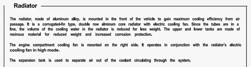
With ordinary production cars, the radiator, the engine and the tank (reservoir) are located closely together.
The (radiator) cap is attached to the filler neck of the radiator and it is the highest point of the cooling system.
With this layout, the tank indeed acts as the reservoir.
There will be a tube running from the radiator filler neck to the tank and the other end of the tube is submerged in the coolant inside the reservoir.
There is another short tube at the reservoir allowing the internal tank pressure to be at the atom pressure so that it can act as overflow tube as well as allowing the air to enter the reservoir to prevent negative pressure when the coolant is returned to the radiator during the cool down process.
As the engine warms up, the coolant expands and the radiator cap controls the system pressure.
When the system hits the pressure threshold, the expanded coolant will be transferred to the reservoir.
Any air that may have been trapped or generated in the cooling system will be captured at the filler neck since it's the highest point of the system and the hot coolant normally enters the radiator from the upper hose.
Then, the captured air at the filler neck will be eventually pushed towards the reservoir to eliminate the air from the cooling system.
When the system cools down, the coolant also contracts and reduces the volume. So, the negative pressure valve at the radiator cap will open allowing the coolant to be returned back to the radiator without any air entering the system.
Every time when you start the engine, drive the car and then park it, it's the repeat of the above process so you need to keep the coolant level above the MIN line of the reservoir.
With this layout, the entire cooling passage is fairly short so the air can be separated without extra process.
Because it's fairly short passage and simple design, the system 'may' have wider margin against the flow friction/drag causing cavitation at the WP.
On our NSX, it's a different story.
The engine is at the back and the radiator is at the front. Therefore, the entire cooling system passage is quite long and needs careful consideration for removal of air for the cooling efficiency and prevention of the cavitation especially at the WP.
I have never measured the reduction ratio of WP pulley against the TB drive pulley but if you have ever worked in this area, you can imagine how fast the WP could be spinning while the engine is running.
From WP point of view, the coolant flow returning from the radiaor could be a friction/drag factor if the flow was not smooth enough and could cause cavitation.
This is probably one of the reason why NSX is using expensive WP compared to the cheap one on ordinary cars that tend to use impeller manufactured from just pressed metal sheet.
I saw several cheap WP impeller smashed due to cavitation because the owner left the coolant service for ages.
You don't need to have visible air inside the system to generate bubbles.
While in the hot bath tab, please try moving your hand side way rapidly in the water to fight against the wall of the water.
If you managed to move your hand fast enough with ideal gap between each fingers, you should be able to generate lots of air bubbles. That's the cavitation and since your hand was already submerged in the water, there was no visible air under the water surface. You can see the same thing happening at the screw of the leisure boat, etc under certain conditions.
Under certain applications, the design of screw becomes top secret.
The force of continued cavitation is enormous. It's like shaving off piece of metal from the impeller surface by each bubbles.
Eventually, you will end up with WP spinning with missing impeller resulting in not enough coolant flow and causing over heating situation.
Bubble can be generated when the coolant goes through that narrow channel around the cyl bore or passing through the small holes/pipes.
Also, if the engine was stopped immediately after driven hard, it can cause heat spot. You will be surprised how some of the journalists stops the engine after the hard test driving session.
You feel like you can really hear the coolant boiling inside the engine......
So, it is important to separate the air from the coolant for the efficiency point of view.
Air can't hold much energy compared to the water.
- - - Updated - - -
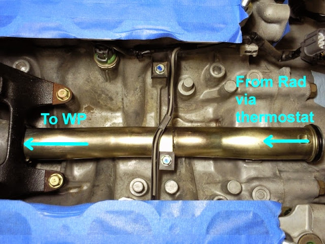
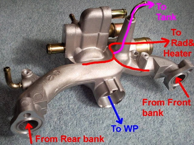
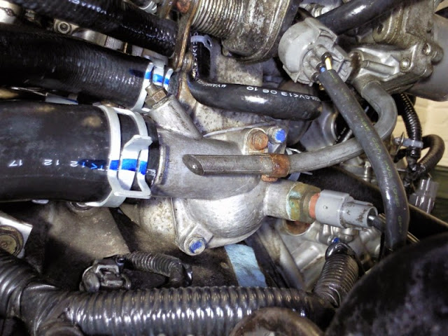
This is the water passage of our engine.
The hot coolant is cooled down at the radiator and then it is returned to the WP through the centre pipe running inside the V-bank under the intake manifold as indicated in light blue arrow (should have used blue arrow instead because it's the same flow as the coolant returning from the radiator via thermostat after being cooled down. It's not the same flow as the one returned from the Heater core indicated in the light blue arrow.....).
Then the WP pushes the cooled coolant from the radiator towards the front and rear bank cyl block.
This will absorb the heat energy from the engine into the coolant while passing through the block and part of the head then the hot coolant from both banks enter the water passage as indicated by the red arrows.
Two flows are merged into one and if the thermostat is open, the hot coolant is sent to the radiator in order to cool it down.
The same flow is used for the heater control.
If the water valve is open but the thermostat is still closed, the hot coolant still travels through the same pipe but won't pass through the radiator and instead, it will travel upwards at the T junction before the radiator and heats up the heater core based on how far the water valve is opened.
If the thermostat (and the water valve) are closed, the coolant simply circulates within the engine to speed up the warm up sequence.
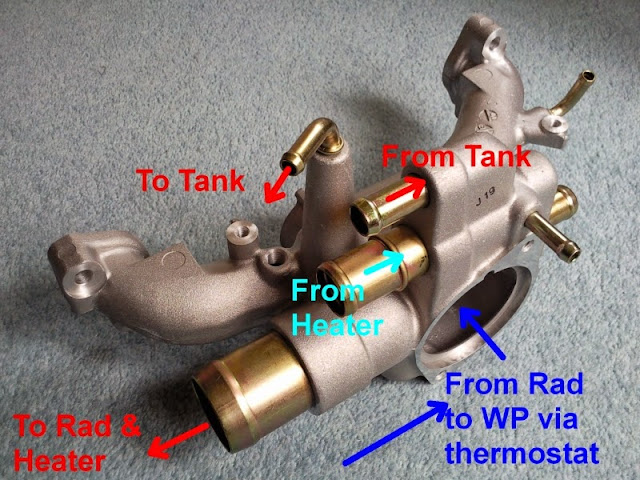
Here comes the nice design.
After the hot coolant from the front and rear bank are merged, in order to filter out the air, there is a chamber built into the water passage body forcing the upper stream of the hot coolant to be passed through the expansion tank as marked in pink arrow.
The air is most likely to be at the upper stream of the hot coolant so this chamber design will efficiently capture the air and transfer it towards the tank.
As soon as you start the engine, the WP starts spinning and thus, this flow towards the expansion tank begins immediately and it will continue to do so until you stop the engine.
If you have OEM tank, you can see the continuous coolant flow from the small hose connected at the upper side of the tank close to the tank cap.
If you adjust your viewing angle, you should be able to see the fast stream of coolant shooting horizontally just below the brass tank neck in the direction towards the front of the car.
Not easy to see in this video but you may be able to see just about a few mm width white stream of coolant below the brass filler neck.
Considering the surface tension of the thousands of tiny bubbles and in order to filter out the air thoroughly from the coolant, it requires enough length of filter passage.
At the same time, the tank needs to be able to hold enough level of coolant as well as enough open space to cope with the increase of volume when the system gets hot.
Within the limited space in the engine bay, Honda decided the size of the tank and designed it with multiple chambers connected with the tunnel (hole) each others inside the tank.
One side of the tank surface is about 25cm x 20cm.
With the tank cap pressure setting of 1.1kgf/cm2, it will be more than 500Kg applied to that single surface/side with thermal shock, vibration and pressure cycling when the engine is started/stopped.
In order to cope against this huge force with the use of plastic resin under severe conditions while filtering out the air from the coolant, each chambers walls were designed in round shape with small capacity.
If similar shape tank was made out of the metal sheet, it will need consideration on the thickness and welding point/spec against this huge force under the above severe conditions so personally, just pressure testing is not enough.
As mentioned earlier, you need to consider the friction/drag of the coolant from the WP point of view for the cooling efficiency as well as for the prevention of cavitation.
If you are thinking of using aftermarket parts such as multi flow/return radiator, you must use the one designed and tested with the above point in mind especially if you are tracking your NSX. Any friction will reduce the flow rate and will increase the chance of cavitation. Some of the aftermarket tripple flow radiators were tested on track using real NSX for more than 12months before they were made available on the market.
It is important to replace the coolant at least at the specified interval.
If we ignore the corrosion, plain water is much better than the 50% pre-mixed coolant from the point of cooling efficiency.
If you track your NSX regularly and live in the area where it won't get super freezing cold, you can dilute the mixture to 30% and replace the coolant every 2 years instead of 5 years for the Type 2 coolant. That's what many NSX owners do in Japan if tracking their NSX.
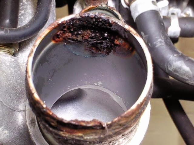
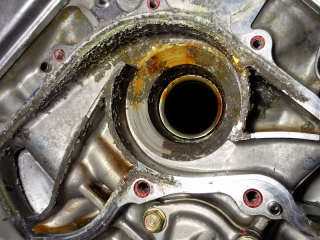
If you didn't replace the coolant for many years like on low annual mileage NSX kept inside museum condition, you may end up with this situation.
The coolant acts as anti-corrosion as well as anti-cavitation. Over the years, the corrosion inhibitor and the chemical (silicone like) for reducing the cavitation will loose their strength.
Eventually, the rust will build up at WP and coolant pipe fitting area.
This NSX looked like never driven under the wet condition so the suspension area, engine bay, the area under the engine, etc looked so clean with almost no rust.
However, once you start opening the engine, you will notice the true story of low annual mileage car.
As mentioned many times in my blog, moisture can enter the engine through the valve left open after you stop the engine and with the air temperature change, it could cause condensation inside the engine. If the car was not used regularly, this moisture will eventually overcome the thickness of the oil film next time when the engine was started. The camshaft lobes showed deeper scratch markings due to build up of moisture from condensation, cooling system was heavily corroded and I actually managed to push my finger through one of the pipe at the water passage.
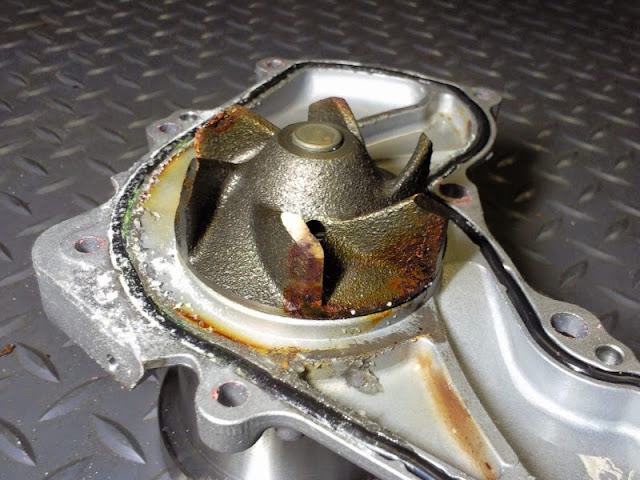
The rust eventually modified the shape of the WP impeller surface and I think it caused small cavitation and grabbed off some of the metal material that is very unusual for our NSX.
Not easy to see in this photo but one of the impeller surface at the back showed lots of tiny dent as if the ice cream scooped out by multiple tiny spoons.
Another reason why I recommend the owner to replace WP regardless of the mileage as you won't be able to check this without removing it.
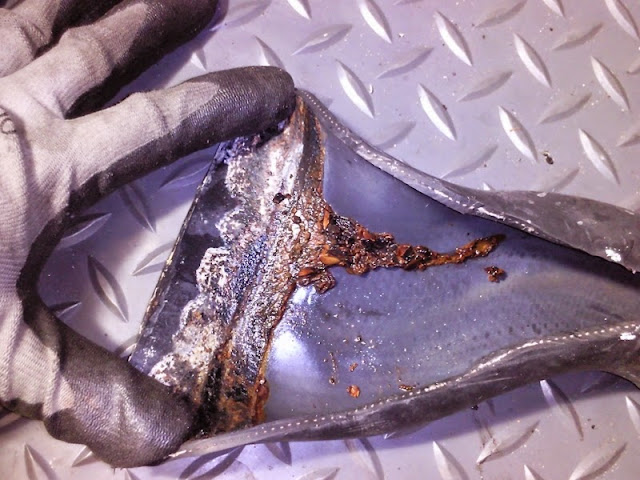
Rust and smashed metal travelled everywhere inside the cooling system so took ages to flush out the debris.
Another reason why I recommend driving it regularly and not just keeping it as a garage queen.
- - - Updated - - -
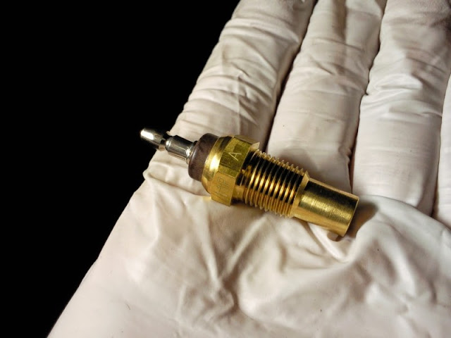
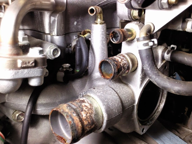
As a side note, there are 3 temperature sensors on the cooling system.
This is the coolant temperature sender unit. It is the sensor for the coolant temperature gauge inside the dash and the sensor is mounted on the water passage that we saw earlier.
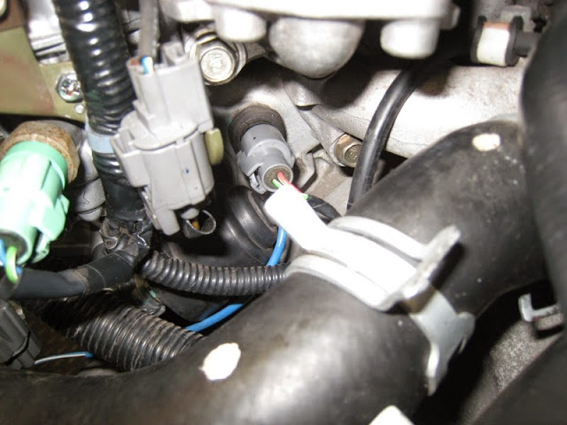
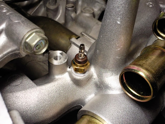
Next is the TW sensor for engine control. It's the one with round 2pin grey connector in the middle of this photo. It's located below the EGR valve and this is the one used for several engine control software modules related to the fuel timer and IG control.
The 3rd one is the thermo sensor at the thermostat cover. This is the one related to the radiator fan control.
All three sensors operate independently so even if your gauge may not be showing the correct temperature, the rad fan and engine control won't be affected.
There is a unit inside the cabin behind the left side seat called Fan Control Unit and this could experience soldering crack (like the Main Relay on many Honda/Acura models) resulting in all sorts of strange behaviour with the radiator fan.
Almost always when it fails, it will switch on the rad fan and both condenser fans when you put IG switch in P2 (ON position) even when the engine is cold and not even started over night.
Kaz
I started writing multiple small topics over the last several days and just started compiling all of them into one piece.
It will take several days if I start talking about the cooling system on our NSX in detail so I'll just touch on the basic.
As each topics were written at different timing, it may sound dis-oriented but hope you will get the idea on the design background.
The main purpose of the expansion tank is the separation of the air from the coolant.
It is also mentioned on the English workshop manual in page 5-15.
With ordinary production cars, the radiator, the engine and the tank (reservoir) are located closely together.
The (radiator) cap is attached to the filler neck of the radiator and it is the highest point of the cooling system.
With this layout, the tank indeed acts as the reservoir.
There will be a tube running from the radiator filler neck to the tank and the other end of the tube is submerged in the coolant inside the reservoir.
There is another short tube at the reservoir allowing the internal tank pressure to be at the atom pressure so that it can act as overflow tube as well as allowing the air to enter the reservoir to prevent negative pressure when the coolant is returned to the radiator during the cool down process.
As the engine warms up, the coolant expands and the radiator cap controls the system pressure.
When the system hits the pressure threshold, the expanded coolant will be transferred to the reservoir.
Any air that may have been trapped or generated in the cooling system will be captured at the filler neck since it's the highest point of the system and the hot coolant normally enters the radiator from the upper hose.
Then, the captured air at the filler neck will be eventually pushed towards the reservoir to eliminate the air from the cooling system.
When the system cools down, the coolant also contracts and reduces the volume. So, the negative pressure valve at the radiator cap will open allowing the coolant to be returned back to the radiator without any air entering the system.
Every time when you start the engine, drive the car and then park it, it's the repeat of the above process so you need to keep the coolant level above the MIN line of the reservoir.
With this layout, the entire cooling passage is fairly short so the air can be separated without extra process.
Because it's fairly short passage and simple design, the system 'may' have wider margin against the flow friction/drag causing cavitation at the WP.
On our NSX, it's a different story.
The engine is at the back and the radiator is at the front. Therefore, the entire cooling system passage is quite long and needs careful consideration for removal of air for the cooling efficiency and prevention of the cavitation especially at the WP.
I have never measured the reduction ratio of WP pulley against the TB drive pulley but if you have ever worked in this area, you can imagine how fast the WP could be spinning while the engine is running.
From WP point of view, the coolant flow returning from the radiaor could be a friction/drag factor if the flow was not smooth enough and could cause cavitation.
This is probably one of the reason why NSX is using expensive WP compared to the cheap one on ordinary cars that tend to use impeller manufactured from just pressed metal sheet.
I saw several cheap WP impeller smashed due to cavitation because the owner left the coolant service for ages.
You don't need to have visible air inside the system to generate bubbles.
While in the hot bath tab, please try moving your hand side way rapidly in the water to fight against the wall of the water.
If you managed to move your hand fast enough with ideal gap between each fingers, you should be able to generate lots of air bubbles. That's the cavitation and since your hand was already submerged in the water, there was no visible air under the water surface. You can see the same thing happening at the screw of the leisure boat, etc under certain conditions.
Under certain applications, the design of screw becomes top secret.
The force of continued cavitation is enormous. It's like shaving off piece of metal from the impeller surface by each bubbles.
Eventually, you will end up with WP spinning with missing impeller resulting in not enough coolant flow and causing over heating situation.
Bubble can be generated when the coolant goes through that narrow channel around the cyl bore or passing through the small holes/pipes.
Also, if the engine was stopped immediately after driven hard, it can cause heat spot. You will be surprised how some of the journalists stops the engine after the hard test driving session.
You feel like you can really hear the coolant boiling inside the engine......
So, it is important to separate the air from the coolant for the efficiency point of view.
Air can't hold much energy compared to the water.
- - - Updated - - -
This is the water passage of our engine.
The hot coolant is cooled down at the radiator and then it is returned to the WP through the centre pipe running inside the V-bank under the intake manifold as indicated in light blue arrow (should have used blue arrow instead because it's the same flow as the coolant returning from the radiator via thermostat after being cooled down. It's not the same flow as the one returned from the Heater core indicated in the light blue arrow.....).
Then the WP pushes the cooled coolant from the radiator towards the front and rear bank cyl block.
This will absorb the heat energy from the engine into the coolant while passing through the block and part of the head then the hot coolant from both banks enter the water passage as indicated by the red arrows.
Two flows are merged into one and if the thermostat is open, the hot coolant is sent to the radiator in order to cool it down.
The same flow is used for the heater control.
If the water valve is open but the thermostat is still closed, the hot coolant still travels through the same pipe but won't pass through the radiator and instead, it will travel upwards at the T junction before the radiator and heats up the heater core based on how far the water valve is opened.
If the thermostat (and the water valve) are closed, the coolant simply circulates within the engine to speed up the warm up sequence.
Here comes the nice design.
After the hot coolant from the front and rear bank are merged, in order to filter out the air, there is a chamber built into the water passage body forcing the upper stream of the hot coolant to be passed through the expansion tank as marked in pink arrow.
The air is most likely to be at the upper stream of the hot coolant so this chamber design will efficiently capture the air and transfer it towards the tank.
As soon as you start the engine, the WP starts spinning and thus, this flow towards the expansion tank begins immediately and it will continue to do so until you stop the engine.
If you adjust your viewing angle, you should be able to see the fast stream of coolant shooting horizontally just below the brass tank neck in the direction towards the front of the car.
Not easy to see in this video but you may be able to see just about a few mm width white stream of coolant below the brass filler neck.
Considering the surface tension of the thousands of tiny bubbles and in order to filter out the air thoroughly from the coolant, it requires enough length of filter passage.
At the same time, the tank needs to be able to hold enough level of coolant as well as enough open space to cope with the increase of volume when the system gets hot.
Within the limited space in the engine bay, Honda decided the size of the tank and designed it with multiple chambers connected with the tunnel (hole) each others inside the tank.
One side of the tank surface is about 25cm x 20cm.
With the tank cap pressure setting of 1.1kgf/cm2, it will be more than 500Kg applied to that single surface/side with thermal shock, vibration and pressure cycling when the engine is started/stopped.
In order to cope against this huge force with the use of plastic resin under severe conditions while filtering out the air from the coolant, each chambers walls were designed in round shape with small capacity.
If similar shape tank was made out of the metal sheet, it will need consideration on the thickness and welding point/spec against this huge force under the above severe conditions so personally, just pressure testing is not enough.
As mentioned earlier, you need to consider the friction/drag of the coolant from the WP point of view for the cooling efficiency as well as for the prevention of cavitation.
If you are thinking of using aftermarket parts such as multi flow/return radiator, you must use the one designed and tested with the above point in mind especially if you are tracking your NSX. Any friction will reduce the flow rate and will increase the chance of cavitation. Some of the aftermarket tripple flow radiators were tested on track using real NSX for more than 12months before they were made available on the market.
It is important to replace the coolant at least at the specified interval.
If we ignore the corrosion, plain water is much better than the 50% pre-mixed coolant from the point of cooling efficiency.
If you track your NSX regularly and live in the area where it won't get super freezing cold, you can dilute the mixture to 30% and replace the coolant every 2 years instead of 5 years for the Type 2 coolant. That's what many NSX owners do in Japan if tracking their NSX.
If you didn't replace the coolant for many years like on low annual mileage NSX kept inside museum condition, you may end up with this situation.
The coolant acts as anti-corrosion as well as anti-cavitation. Over the years, the corrosion inhibitor and the chemical (silicone like) for reducing the cavitation will loose their strength.
Eventually, the rust will build up at WP and coolant pipe fitting area.
This NSX looked like never driven under the wet condition so the suspension area, engine bay, the area under the engine, etc looked so clean with almost no rust.
However, once you start opening the engine, you will notice the true story of low annual mileage car.
As mentioned many times in my blog, moisture can enter the engine through the valve left open after you stop the engine and with the air temperature change, it could cause condensation inside the engine. If the car was not used regularly, this moisture will eventually overcome the thickness of the oil film next time when the engine was started. The camshaft lobes showed deeper scratch markings due to build up of moisture from condensation, cooling system was heavily corroded and I actually managed to push my finger through one of the pipe at the water passage.
The rust eventually modified the shape of the WP impeller surface and I think it caused small cavitation and grabbed off some of the metal material that is very unusual for our NSX.
Not easy to see in this photo but one of the impeller surface at the back showed lots of tiny dent as if the ice cream scooped out by multiple tiny spoons.
Another reason why I recommend the owner to replace WP regardless of the mileage as you won't be able to check this without removing it.
Rust and smashed metal travelled everywhere inside the cooling system so took ages to flush out the debris.
Another reason why I recommend driving it regularly and not just keeping it as a garage queen.
- - - Updated - - -
As a side note, there are 3 temperature sensors on the cooling system.
This is the coolant temperature sender unit. It is the sensor for the coolant temperature gauge inside the dash and the sensor is mounted on the water passage that we saw earlier.
Next is the TW sensor for engine control. It's the one with round 2pin grey connector in the middle of this photo. It's located below the EGR valve and this is the one used for several engine control software modules related to the fuel timer and IG control.
The 3rd one is the thermo sensor at the thermostat cover. This is the one related to the radiator fan control.
All three sensors operate independently so even if your gauge may not be showing the correct temperature, the rad fan and engine control won't be affected.
There is a unit inside the cabin behind the left side seat called Fan Control Unit and this could experience soldering crack (like the Main Relay on many Honda/Acura models) resulting in all sorts of strange behaviour with the radiator fan.
Almost always when it fails, it will switch on the rad fan and both condenser fans when you put IG switch in P2 (ON position) even when the engine is cold and not even started over night.
Kaz
Last edited:
Kaz
Thank you very much for the detailed explanation of the NSX cooling system.
It's no wonder that in the 100k miles I've driven my NSX the temp gauge needle rises to a point just below halfway and never changes, no matter how hard I drive, or how hot the outside air temp.
I am continually amazed at how much engineering has gone in to every part of the NSX and that's why it is so reliable.
Thank you, Kaz! The NSX community is the best.
Thank you Kaz for that excellent description of the system. I'm definitely sticking with the Honda factory tank and will just replace it as a consumable part along with the hoses.
Kaz, thank you. Just read this and feels it needs a bump. The depth of knowledge and detail here blew me away. Wonderful stuff.
Kaz, thank you. Just read this and feels it needs a bump. The depth of knowledge and detail here blew me away. Wonderful stuff.
well-bumped. I reread this and it made me glad I replaced my old oem coolant tank with a new OEM one a couple of years ago.just looking at it,i had no idea so much thought and engineering went into it.
Similar threads
- Replies
- 8
- Views
- 573
- Replies
- 11
- Views
- 746
- Replies
- 51
- Views
- 3K