• Protip: Profile posts are public! Use Conversations to message other members privately. Everyone can see the content of a profile post.

Big McLargeHuge’s 1990 JDM NSX Adventure Thread

How are you going to make the Type R clutch pedal fit? On the page for it on Mita Motorsport it says it only fits RHD cars. If it works on LHD cars I might have to do that.

Edit: Nevermind, I completely forgot that your car is RHD. :rolleyes:

Well, besides being RHD only, this pedal does have that little piece with the stopper on the end that sticks out of the top, and it looks like people end up cutting it off. I guess the bracket design is different for later year cars but it doesn't look like it would hit anything on my car. I don't remember seeing a short travel pedal option for LHD cars since they were only on Type R's (and maybe Type S's but the Fancy-Craft site author was also unsure).

Pic of it cut off here (https://fancy-craft.firebaseapp.com/NSX/report/at-mt/photo/01-05.jpg).
01-05.jpg


Man you have McLaren F1 Gold Foil engine coating on your NSX, that supper cool.

Im surprise that someone let you take stuff that car...or it not picked up for spares....post pictures of the F1 next time you see it.

Bram

Well I wish there was actually an F1 anywhere in GA, lol...I actually got this Reflect-A-Gold sheet here if you're curious (https://smile.amazon.com/gp/product/B0039Z1URK/ref=ppx_yo_dt_b_asin_title_o06_s03?ie=UTF8&psc=1). Hoping it lasts a long time since it's the expensive stuff rather than a copycat product.

I'm wondering if some of the fitment issues you had with the headers and where the flanges are located and the clearance is due to the A/T? From what I've seen most of the companies doing aftermarket headers/exhaust typically only state they fit M/T and they "may" fit A/T. Either way, glad to see you have a temporary solution figured out and I'll be curious to see if the fitment issue is there after the M/T goes in...provided you don't have the flange moved prior to that.

...on to page 5...:biggrin:

I don't believe the fitment issues have to do with A/T vs. M/T. The only clearance issue I had with the A/T was that I had to remove the large black metal cover on the backside of the trans for the rear headers to clear. I don't think it's strictly necessary, but probably part of the reason why most aftermarket headers are M/T only since the A/T case looks larger.

The issues with the manifold flange hole spacing were due to improperly drilled holes which was confirmed by Pride. Hopefully they address that for future production of the V2's.

The last issue with the rear header adapter & test pipe flange hitting the "rod A"/U-bracket should still be a problem with a M/T. The transmission doesn't affect where the flanges or the bracket sits so I don't expect it to help. I bought some new hardware (longer 14mm bolts and spacer washers) to see if that buys me enough clearance. If it doesn't I'll probably have to spend another 2 hours of TIG labor to have the flanges moved which is annoying.

Thank you all for bringing us into a new page :cool:
 
Trans Rebuild pt5.5

That's two properly selected shims installed after 3 tries. With shims I+A (from the 6-speeds), I get 0.16-0.17mm final mainshaft thrust clearance which is perfect. For the diff, shim Y increased my preload just enough to ~18 lb-in which is on the low side but within spec. If I wanted to try and get higher, I'd have to get or make a custom thicker shim which is definitely not worth the effort.

I have a theory that the tolerances for the new differential parts (taper bearings?) are different enough that the standard preload shim table needs to be shifted up to the higher end. If I was rebuilding an A/T differential with the higher range for preload there's no way that the OEM shims would be thick enough.
O8pLWnM.jpg


I know it's not necessary but I replaced the snap ring as well. Like other said it's pretty annoying to get out of the case so they leave it in, I ended up using my fingers from either end to compress it enough to slip out of the case groove, tools were too cumbersome to get a good enough grip. I figure that even though my case is not a "problem child" with an improperly cut groove, the new ring gives me more piece of mind that it won't randomly break from stress.
Q7PLzKD.jpg


Here's me test fitting the old NM speed sensor I replaced from my A/T to the NC sensor spot on the 5-speed. Like more experienced NSX experts have said (LarryB and Kaz), the 4.23 ring is just large enough to hit the end of the sensor which eventually will kill it. I read this wasn't a design case since the 4.23 was never offered with EPS, so this situation is fairly rare and it's fortunate the experts shared their experience so I didn't end up destroying my new sensor and getting stuck diagnosing an issue that would only show up after driving the car for a while.
L8W96b4.jpg


With a normal washer, I can buy enough clearance to keep the sensor intact. This is just a test, I'll get a properly sized one to install permanently. Not sure how far away the sensor can be without messing with the (magnetic?) signal pickup for the EPS speed signal but I think this should work.
rosGGsm.jpg


Just putting stuff back on. Here's the new oil strainer parts. I cleaned off the metal cap and put some silicone grease on it so that it would be easier to remove in the future from under the car.
3BcAXFI.jpg


Old vs. new release guide bearing. Old one probably would clean up okay, but had some deeper grooves on it so I got a new one from JP for fairly cheap. All in the name of longevity.
QHGJT76.jpg


Staked the countershaft locknut
DkSJwTG.jpg


Installed the trans case diff oil seal. I'll put the clutch side one on but I'd need to lift the diff out again which is a pain since it's so heavy.
vzGkaDt.jpg


Other misc. stuff going back in. Oil pump, countershaft bearing & new staked bolts. I would have put the shift lever back in except that I accidentally only ordered one shifter oil seal because of how the Honda parts diagrams lay them out (says qty 1 required for the car). Ordered another from the local Acura dealer and should get it by Tuesday.
6QqBfmG.jpg


Really not much left to do here. Put the release guide & seal back on, select & diff oil seals, then I can actually put all 3 shafts back in for the last time and seal the cases up. I want to block out a day for that stuff so I don't rush and mess something up so I think next weekend will be when I finish everything. This weekend I'll try and fix the exhaust fitment if I get enough courage to get back in the shop with how absurdly hot it is inside. Metal warehouses feel like a school solar oven project from the inside.
 
I have a theory that the tolerances for the new differential parts (taper bearings?) are different enough that the standard preload shim table needs to be shifted up to the higher end. If I was rebuilding an A/T differential with the higher range for preload there's no way that the OEM shims would be thick enough.

FWIW when I replaced my diff bearings the preload was spot on without even changing the shims. I think it just comes down to luck.
 
Final Exhaust Shtuff

FWIW when I replaced my diff bearings the preload was spot on without even changing the shims. I think it just comes down to luck.

Probably right, I had one other data point where whrdnsx also had to go custom for preload shims. Hopefully Honcho has an easier time than I did.


Here's what I keep talking about with the exhaust fitment issues. This flange is being pushed up by the bracket below and is putting stress on the pipes all the way up to the front headers.
vyb2HMi.jpg


This is how much the flange pushes on the bracket when the bolts are taken out. Part of the reason why I was hesitant to use washers as spacers since it's like 1/3" of interference. I bought some thick M10 washers from McMaster-Carr and M10 JIS bolts that were longer than factory to make sure they threaded in the same amount. They're zinc coated similar to the old Dacro coating but I'm not sure how much corrosion protection they will have vs. stock so I'll keep an eye on them over the next few months. Again, the underside looks worse than it actually is, the black coating on the aluminum is just old and flaking off all over, and the bolt heads look corroded but I haven't had any trouble getting any of the bolts out so far.
DLURbYs.jpg


Here's what it looks like now. The new bolts torqued down to spec just fine, and I added a strip of high-temp rubber under the flange to prevent rattling. The flange isn't hitting the bracket anymore but I would've preferred to weld the flange somewhere else, it looks a bit odd with three thick washers like that. It was a fairly easy fix and I think it'll work just fine.
ioPBM7M.jpg


My last fitment issue was that when I tightened down the test pipe all the way, because of how the flanges are angled, it would pull the left-hand exhaust tip frontward and mess up the tip alignment with the rear valence. I loosened a few other flanges along the exhaust to get some extra play, but to solve this completely I'd need to drill out the flange bolt holes a few mm larger to get the extra play I need to eliminate the misalignment on these two flanges.
UY3XUJW.jpg


Final overall pic of the system. I got it about 80% of the way there, to the level that it still bothers me a little bit but most people would not notice the alignment of the tips.
ugdOcDb.jpg


I'm still happy with this project in the end, sounds fantastic and definitely feels faster punching it at certain RPM's. I feel like I also get more attention from other drivers now it's louder than most other cars on the road...several people revving at me at lights, pacing me, even one pointing me by on a normal surface road which was a bit odd. Every drive is special at least :biggrin:.

I haven't gotten around to taking a video yet but I'll add an edit to this post with a YT link soon. No idea how it'll come across with my phone's audio.
 
The crossmember thats hitting the flange looks to be bent pretty badly, perhaps that's why it's hitting?

That's disappointing quality from Pride though...my Pride V1 exhaust system has fitment issues too, I had to buy adjustable hangers to get it level but one tip still sticks out more than the other. I think [MENTION=18194]Honcho[/MENTION] has Pride headers too so hopefully his aren't this problematic.
 
Last edited:
It could be, I noticed it was bowed upwards slightly but wasn't sure if it was supposed to be like that, I didn't have any issues bolting it up. Someone could have used it as a jack point or something in the past.

I'd still buy the Pride stuff again but would wait until they fix the issues with the V2 headers. Mine, Honcho's, and Remi's had the missing O2 bung/flange pattern/bolt hole issues but that should be an easy fix for future batches, they're aware of the problems and have been decent at helping fix them.

Finally got around to taking a video in a back lot with my phone propped up. With the long 4-speed gearing of the A/T I can't really go fast enough to upshift with a limited runway but you get the idea. Super loud at any substantial throttle pressure, but with light application to let the A/T upshift smoothly it's barely louder than stock even at cruising speeds with open windows. Another reason why I can't wait to put in the 5-speed, I should be able to redline in 1st and 2nd whenever I want without getting arrested ;^). The most I can do with an automatic is floor it and most of the time it'll downshift to 2nd, which is also very tall.
https://www.youtube.com/watch?v=EzEIjTB2Uq4
 
Last edited:
In Their Clutches

Great progress, and as always very well documented for posterity :cool:
:biggrin:

One odd issue with parts procurement I ran into is the clutch pedal collar, which is the axle around which the pedal bushing rotate. The part number for the one that fits the JDM clutch pedal bracket (with one switch) is not available in North America and is backordered for a long time in Japan. I was thinking about trying junkyards or making my own but I decided just to order the US part #.
roiTCG6.jpg


The LHD/2-switch bracket must be wider because the Acura part is too long to fit inside my bracket. Fortunately with a Dremel, anything is possible.
MS4Ray0.jpg


Once I had measured the cut twice, cut once, and sanded the edge smooth, I fit it to the bracket with the pedal and through-bolt. Fits perfectly. Much easier than the alternative options.
MTWioiz.jpg


Another issue to solve that I've been ignoring is the A/T cooler bypass. Supposedly you can use the factory longer hose to bypass the A/T fluid cooler (obv. not used for a M/T) but I wanted to come up with a good solution before I got stuck under the car without something that actually works. The hose from the thermostat housing normally loops through the A/T cooler to the oil cooler on the filter housing and back. Maybe I'll also have cooler oil temps from this?..

I ordered two sizes of vacuum-rated coolant hoses from McMaster-Carr with my exhaust hardware previously that I can cut to whatever length I want. I ordered the stock A/T hose to compare diameters but it's backordered for now, so I fit an OEM clamp on the hose to see if the sizing was close. The clamp fits nicely on one of the hoses (forgot the spec I ordered) so as long as the inner diameter is close then I can use this solution for A/T cooler bypass and it should last a long time.
Nkr4KRF.jpg


Next is the conclusion of the epic saga that is this transmission rebuild.
 
Last edited:
Trans Rebuild pt6 (Final)

ouGlVX7.jpg


We finally did it. Details below.

Input shaft oil seal, diff oil seal, and new release guide bearing installed. Pretty simple with proper seal drivers.
zPXprHt.jpg


Select lever installed with the new oil seal I just got.
Differential put in for the last time, with the new NSX-R oil pump drive gear to match.
Main & countershafts zip tied together with the cleaned shift forks & shafts and dropped into place. This was easier than expected, only took maybe 5 minutes.
Reverse gear & shaft installed. Luckily someone was in the shop with me and helped lift the main/countershafts up a few mils which let me slip the two reverse shafts in their holes. Possible with one person but is more of a 3-4 handed effort.
IBmzLJw.jpg


Change assembly and reverse shift link installed after cleaning off the parts, bolts, holes, etc. and torquing everything to spec. Everything so far pretty straightforward.
PwwWNVG.jpg


We haven't even gotten to the worst part yet, which is sealing the cases back together. I did several dry runs to figure out my method for getting them together reliably, there's several shafts and bearings and shift links that have to line up exactly for the top case to drop completely so it's pretty annoying. Motormount's rebuild thread I've posted before has some good tips that made it a bit less annoying.
fgZD8rZ.jpg


The gap between the cases is because the snap ring left un-expanded sits on top of the countershaft bearing instead of its groove. There are 3 methods I've heard to get the countershaft up the few mils to line the groove up with the snap ring, I chose the dumbest one by far first and paid the price.
gNeY83G.jpg


Once I started the clock with applying the Hondabond sealant, I hurried to get the cases mated and got to the same point as before, and tried a method I read about which involved hand-tightening a few bolts on the cases, flipping the whole transaxle over with the ring expanded, and tapping or shaking the case to get the shaft bearing groove to drop into the ring. This was very dumb. Some leftover oil in a dank crevasse decided to leak all over my sealant and ruin everything. Cases had to be pulled back apart and I wasted another 2 hours scraping off the still-drying sealant and re-cleaning everything. Very frustrating.
XX6p3k6.jpg


If that wasn't enough, while I was applying the sealant the back seam blew out and covered my gloves in a huge grey blob. The next go-around this morning I used some clamps to hold what was left of the sealant inside the tube so I could use it for the second try.
2eVpsnK.jpg


Anyways, it was late in the night and I waited until this morning to try again. Not many pics of this since reassembly is pretty easy, but this time after applying the Hondabond and got to the snap ring, I expanded it until it was almost the same diameter as the bearing and used a long screwdriver/pry bar on the bearing groove to gently lift the countershaft up instead of flipping the trans over. This actually worked really well, after a minute or two the ring "snapped" right into place in its home and all was right in the world.
pltmTlH.jpg


Right after that, I put in all 16 case bolts for the millionth time for a final torquing while the sealant is setting. Went easily since I had done this so much already with the mainshaft/diff shim measurements.
rBmt4xS.jpg


And then....you put everything else on. The FSM covers all this so nothing difficult or confusing really. I had bagged and tagged (and marked) everything in its original position so the two months in-between disassembly and reassembly wasn't too bad.
7GqVv2W.jpg


Everything put in on the other side. New top sealing bolt, new breather tube assy, new reverse gear sensor, old VSS and neutral switch, etc. etc. This was all gravy at this point. Still need to either buy the speed sensor for the EPS signal or wait until I can steal it off of my A/T during the swap.
a074fMR.jpg


Well, that's it. Besides sealing the cases, everything else went pretty smoothly. The shifts are smooth too (I tested during the dry runs) so that's reassuring.
Ri44oAw.jpg


Here's a short vid of me shifting through the gears after final assembly. Goes into every gear easily, snaps back like it should, all the detents seem to be working right. Of course, the true test is running it in the car but we'll have to wait until then to see how good of a job I really did.
https://www.youtube.com/watch?v=WqJtxWDBtUI

Feel free to send me gift cards, pizzas, etc. and we can celebrate this together. It's been a long time coming, over two months since I started with multiple parts orders from overseas plus the extra time spent from this being the first time I've done something like this. Total time spent was probably 50+ hours or something stupid like that (really 100+ with all the research I had to do), but I really stopped counting a while ago. Hopefully my insistence on being thorough pays itself forward for the coming years. Thanks again to Motormouth for this post (http://www.nsxprime.com/forum/showt...Transmission-Rebuild-Thread?highlight=AMAYAMA), I probably couldn't have done it without him.

Very few things left before I can take the week off for the swap, I have 99% of the parts I need and the ones I don't have are easy to get so I left them for last.
 
Last edited:
>Another issue to solve that I've been ignoring is the A/T cooler bypass. Supposedly you can use the factory longer hose to bypass the A/T fluid cooler (obv. not used for a M/T)

You can use the stock AT hose, but it's a bit taunt.

> but I wanted to come up with a good solution before I got stuck under the car without something that actually works.

I saw the post on coolant pressure sensors and thought that was a really good idea, this might be a good place to implement it and one has hoses ready to go.

An low oil pressure sensor is about the same pressure as no coolant, which can be sourced from the boneyard. A future project for me no doubt, super cool idea.

Just need an inline 1/8 NPT hose adapter. The hardest part is getting wires inside the passenger compartment.

>The hose from the thermostat housing normally loops through the A/T cooler to the oil cooler on the filter housing and back. Maybe I'll also have cooler oil temps from this?..

? you are planning on repurposing the AT cooler? It is a liquid to liquid cooler, not sure how much it would help.
 
Does the stock A/T cooler hose have a 90-degree-ish kink in it? I haven't seen the geometry in person but if the bypass is a straight run I wouldn't want to bend the stock hose straight since it would stress out the elbow and might fail prematurely.

The coolant pressure sensor is definitely a good idea. I might add one during my upcoming compete hose & radiator replacement.

Sorry if the A/T cooler part was unclear, I meant that by removing the stock cooler, the coolant going to the oil housing will be colder since it doesn't have to take heat from the ATF. Might save a few degrees?
 
Here's a short vid of me shifting through the gears after final assembly. Goes into every gear easily, snaps back like it should, all the detents seem to be working right. Of course, the true test is running it in the car but we'll have to wait until then to see how good of a job I really did.
https://www.youtube.com/watch?v=WqJtxWDBtUI
Well done.

While I have to admit that the camera is needed for the other hand...:) this test needs both hands to check the lockout but I'm pretty sure you did.
 
Absolutely amazing process and documentation. You deserve a beer, or maybe six. Thanks for sharing.
 
Well done.

While I have to admit that the camera is needed for the other hand...:) this test needs both hands to check the lockout but I'm pretty sure you did.

Correct ;^). Seems dumb but how do I check the lockout? Rotate the mainshaft with one hand and try to stick it in reverse?

Absolutely amazing process and documentation. You deserve a beer, or maybe six. Thanks for sharing.

Thanks for the kind words. I treated myself to a quality plate of several dozen chicken wings that night.

More to come in the next few weeks.
 
More unfortunate news, the SoS clutch kit I ordered is only coming back in stock around Aug 21, so at least another 3 weeks of waiting. I might start taking apart the interior in the meantime and making my wiring harnesses for when the time comes to make it go smoother, which will still let me drive the car with some weight reduced. Maybe I'll even put in a vestigial clutch pedal :rolleyes:

On the bright side, *both* my S2000 clusters have now reached Sweden this week. I shipped off the replacement cluster just a few days ago, and that same night I got the first update on the original USPS-shipped cluster in over 3 months when I thought it was lost for good, so I paid the extra $200 shipping for nothing. At least both of them are in good hands and not lost at sea. Once I get one complete cluster back I'll have time to swap it over and test it before I put in the M/T to avoid creating multiple problems at the same time.
 
Last edited:
Trans Swap Prep & Cluster Swap pt1

While I wait for my new cluster to arrive, I wanted to start taking apart the interior to give myself easy access for the cluster and transmission swap coming up.

Still can't drive the car until I put the cluster in so the mileage doesn't change since it's programmed by Johan in Sweden before being shipped back here.

As always, some interesting discoveries with a 30 year old car of unknown provenance.

Here's the bulk of the stuff taken apart. I've taken the cluster out once before so this time was easy. Now all I have to do is unplug the two connectors and undo 4 screws and it'll come out.

It was my first time taking the center console off but there's several DIYs readily available online. Someone had taken it apart before me judging by how easy it was to get the vent piece off, must've broken a clip or two previously. I didn't notice until taking it off.

y0NMb6q.jpg


Rear bulkhead panels taken off. Second time for me so I knew where all the clips were already. I'll probably end out taking a seat or two during the swap to give me more room to work, but I might be able to make do.
QQ4waRv.jpg


There was this odd aftermarket blk/red wire that went to nowhere that I need to trace back. It goes up the left side under the carpet so I'll need to disassemble a bit more to see what the deal is. It isn't even stripped on the end so it wasn't being used for anything.
ZKwfpgp.jpg


The biggest annoyance by far was taking the lower dash brace bar off. Someone else had nearly stripped out one of the screws and my non-JIS screwdriver wasn't enough so I had to use vice grips on the top threads of the screw to loosen it enough for the screwdriver to finish the job. They had also broken off this side of the lower dash under the IGN switch so it was just flopping around. I suppose I don't need to worry about doing that myself now when taking off the steering column but it will be hard to glue back together with the dash still in place.
swNp2lZ.jpg


This gave me the chance to test out the OEM Sumitomo connectors I got from Cycle Terminal. This is the 12P connector for the shift console switch, as you can see, the new one is an exact match and will let me make my own harness without modifying the factory wiring.
koD5D4q.jpg


The A/T safety switch was a different brown connector design so I might just de-pin the shifter side and make a loop on it to permanently close the circuit.
DuN8Hm8.jpg


Similarly, this 20P connector next to the ECU will let me patch in the clutch switch and neutral switch inputs. With the new male/female terminals and 16ga wire I'll make a short patch harness to keep the OEM harness fully intact. Should be pretty simple with the right tools.
5clnBsB.jpg


The most odd thing I found was this ordeal. It looks like this part of the harness for the cig lighter & lights was just grounded to the shifter base with those two green wires for some reason, and the other end of a wire was soldered to the banana plug that slips onto the end of the lighter on the center console. I've never used the lighter before so I never noticed it wasn't connected, though I suppose when I first bought the car I tried to put in a bluetooth adapter there that didn't work but I thought it was the adapter.
lPmY5fh.jpg


That should explain it. This 3P connector to that harness had what looked like a melted pin terminal, maybe after that happened someone just...decided to ground the lighter harness? Might be due to an overcurrent from something plugged into the socket melting this connector or something. I have a spare 3P connector so I'll try to de-pin this one and put a new one on and see what happens. I guess this isn't the worst thing I could've found.
TE9zFQG.jpg


Here's another pic. Don't quite understand the logic used here.
sukiuOp.jpg


On the plus side, when I took the climate control unit out to replace the capacitors like the rest of the circuit board I've already fixed, I noticed the faceplate and case looked newer than I expected, and I've never had problems with the controls before.
Z9le7MD.jpg


Someone must have replace the CCU entirely in the past, I'm assuming because they were experiencing capacitor failure. The circuit board looked brand new, I could eat a full course Golden Corral buffet off it. I ordered the new capacitors anyways since everything's taken apart already, and replacing the old ones should be very easy with no other trace repairs needed. Thanks, previous owner(s).
2qizzF6.jpg


So far so good. My connectors all fit properly, nothing too bad was uncovered by taking the console off, and the new S2000 cluster and SoS clutch kit are <2 weeks from arriving. The cluster should go in easily and I'll probably go ahead and make the swap harnesses soon. Aiming for either the last week of August or first of September to take my "vacation" days and hopefully come out with a functioning manual car at the end of it. Stay tuuuuuunnneeeddddddd
 
Trans Swap Prep & Cluster Swap pt2

Special delivery. Everything new must be inspected by cat before being put into service. Maybe it's something about international package customs.
iZu8gsi.jpg


Another package containing the replacement capacitors for the CCU also came in, so I spent a little while replacing the old ones. Easy in a way since the old caps looked perfect anyways, difficult since my soldering iron struggled to put enough heat onto the board to melt the solder into my wick. Might have something to do with the large ground planes on some parts and the stock conformal coating gumming things up.
mlTudWu.jpg


Signed by yours truly. This will be worth something someday.
U0j7bpT.jpg


All functions still work. I did notice that there was no backlight on the knobs or the bottom buttons with the DRLs or headlights on, I haven't noticed them not working before so I'm not sure if they've ever been on, most likely the bulb are out but I'll pull the CCU out again and connect the bulbs directly to the battery and test them.
kmZhIFS.jpg


Little side project, I finished sanding, priming, and refinishing the wiper arms with SEM satin black trim spray. Good stuff. One less piece of fading trim on the car.
zoN3HZ1.jpg


Back to the main event, I used the stock gauge visor and finished the assembly of the S2000 cluster to the stock brackets. Johan @ https://www.sjoebergdesign.com/ did most of the work modifying the cluster itself, trimming extraneous plastic nubbins, filing things down, and installing a Qube LED conversion as well ;). All this together was a big investment for me, but there's a lot of advantages I get from this project. The main two are having a functional tachometer for my manual shifting and having a MPH readout to I don't have to keep mentally converting from KPH.

Little uninteresting story time, I sent out my first AP2 S2K cluster to Sweden via USPS back in...April? The package ended up waiting to get on a cargo ship to the EU with zero updates for over Four. Months. At that point I had given up on it, purchased another cluster, and paid a cool $200 for DHL to ship it. The exact night I shipped out the new cluster, I got the first update on the original for months saying it was in Sweden customs, and both were delivered in the same week. Fortunately Johan purchased the extra one from me so I was only out the shipping. He quickly modified my cluster and shipped it back this Monday, package came Wednesday and these pics are from Wed. night :). I had waited around long enough already.

I didn't get the cool foam insert hard case, but everything fit well including the 3D-printed brackets which is impressive with that type of material. I got the black trim plate as well which fits & looks great. My install with the old cluster out was about 2 hours.
h9U9XpY.jpg


Here's a pic of the cluster powered on (before I got it) since my camera struggles with auto exposure settings. The Qube kit & custom multicolor LED template set me back more than I liked but I think it was worth it. Nothing wrong with the stock amber color but I like the green for a sort of 80's retro look, and the colors up to redline on the tachometer will be so much easier to see than the stock tach during enthusiastic driving.
AF4IcvH.jpg


Here's a pic of the new cluster actually installed. As you can see, anonymous future owners, the mileage was matched exactly from the old cluster to the new one at 73,349 km. Of course, imported cars (or anything with a mechanical odometer) are notorious for odometer rollbacks or other fraudulent seller tactics, but I have some other historical info from Japanese gov't records that corroborate the displayed mileage. Thought I'd throw that out there, I personally don't care about mileage much at all, there's plenty of well-maintained 150k mi cars that I would much rather own to drive than a 30k mi car left sitting, but I wanted the continuity of mileage from the old to the new cluster regardless.
R0Yic0I.jpg


Here's my crappy pic with the cluster installed. The mileage actually changes to miles when I change the speedometer to MPH which I didn't know before.

I also learned the auto trans shifts up in 1st gear at 7000 RPM and shifts at 7500 RPM (A/T redline) from 2nd-3rd. Is the lower 1st gear shift point for power curve purposes? Not sure but it shouldn't matter for long.
YiGtf5A.jpg


Another project completed & filed away. Very happy with this one, lots of functional & aesthetic benefits. This S2000 conversion kit offering works perfectly (minus one easy to fix fuel gauge inconsistency), fits well, and Johan is great to work with, so I'll join the chorus of other owners recommending this kit from Sjoeberg Design & Prototyping.

The M/T swap is planned for the week of Aug 31 to Sept 4, the SoS clutch kit is scheduled to ship out tomorrow, and I've made a list of Preparations from A through H for the work. It's not a traditional way to spend vacation time but I'm both excited and nervous to get this done, it'll be a massive hurdle cleared in my long term plans for the car. Plenty of posts coming up.
 
The S2000 cluster looks tiny in the NSX bezel. Are you worried about the green lights clashing with the amber lights in the rest of the interior?

I believe the original CCU boards on early cars had an "AN ETERNAL SPORTSMIND FOR YOU" label on them next to the part number, if it doesn't have it then yeah I'd suspect it had been replaced as the newer cars don't have it. But yeah desoldering through hole components with soldering wick sucks, I did that on a few of my cars boards before switching to a vacuum pump soldering iron when I chipped the ECU and that makes it much easier.

That's a weird connector to be melted, I'm not sure how that could have happened unless somebody bypassed the fuse for that circuit. Did the fuse box seem fine?
 
Last edited:
The cluster is small compared to stock, yeah. In the driver's seat I think it fits perfectly inside the top of the steering wheel; I actually like how compact it is especially if you had a smaller diameter wheel. I think the tach/speedo is much easier to see as well, with this setup you don't even have to look down and you can see what RPM you're at which will be good for me as an inexperienced manual driver. Same info (but with digital battery indicator/no oil gauge) but more compact.

I spent a while thinking about which LED color palette to choose, normally I like matching the light colors inside the car (I'd never put in one of those super bright blue single DIN head units) but I personally like the green LED look a lot. Once I replace the stock radio it'll really only be the clock and CCU that are still amber. This palette's inspired by the C4 digital cluster, very vaporwave.

L2w7Z7U.jpg


I didn't see an Eternal Sportsmind which makes me a little sad now. Got a part # :wink:? I've never used a solder vacuum since I've had that wick spool ever since I started soldering, but since I rarely do any SMC work with all these old boards I should really get one.

The cigar (hmm) lighter fuse looks fine, normal 20A. Why they decided to not fix it at all confuses me. I think that if I just get rid of the green wires to the shifter base and fix the connector, it should work again. Unless there's some other big short in the wiring somewhere else.
 
Cluster looks great! I agree it adds to the retro-futuristic vibe of the car.

Looking forward to the manual swap posts [emoji106]

Thanks! The more I drive with it the more I like it.

Still waiting on SoS to ship out the clutch kit & damper delete. Should be early next week ideally.

EDIT: Now delayed by another 1.5 weeks to early September. Whoopee.
 
Last edited:
Transmission Swap pt1

Months of planning and parts collecting all comes down to this week. I'll split up the posts by day to make this project easier to follow along.

Here are some sources & references I'm using. I have a huge parts list to share as well if you'd find it useful.

FancyCraft - JP blog site for parts lists, walkthrough, wiring, etc. One of the most helpful sources of info especially for RHD cars but missing some info. https://fancy-craft.firebaseapp.com/NSX/report/at-mt/report1.htm
Drew - He wrote his own swap guide which is my main basis for the project. He can provide it if you ask, I haven't asked for permission to distribute it yet. http://www.nsxprime.com/forum/member.php/5430-drew
Wayne - Provided the majority of the RHD swap parts and also wrote the guide for it. http://www.nsxprime.com/forum/member.php/10956-whrdnsx
Cycle Terminal - OEM connectors for wiring harnesses, tools, wiring supplies. http://www.cycleterminal.com/index.html
Speedhunters "Project NSX" - good read for inspiration and some extra info. http://www.speedhunters.com/2018/03/project-nsx-manual-transmission-swap/
NSX1 Blog - Shifter parts, short shifter install. http://www.nsx1.com/shifter.html
Acura factory service manual volumes 1 & 2, NSX Electrical Troubleshooting Manual (1992)

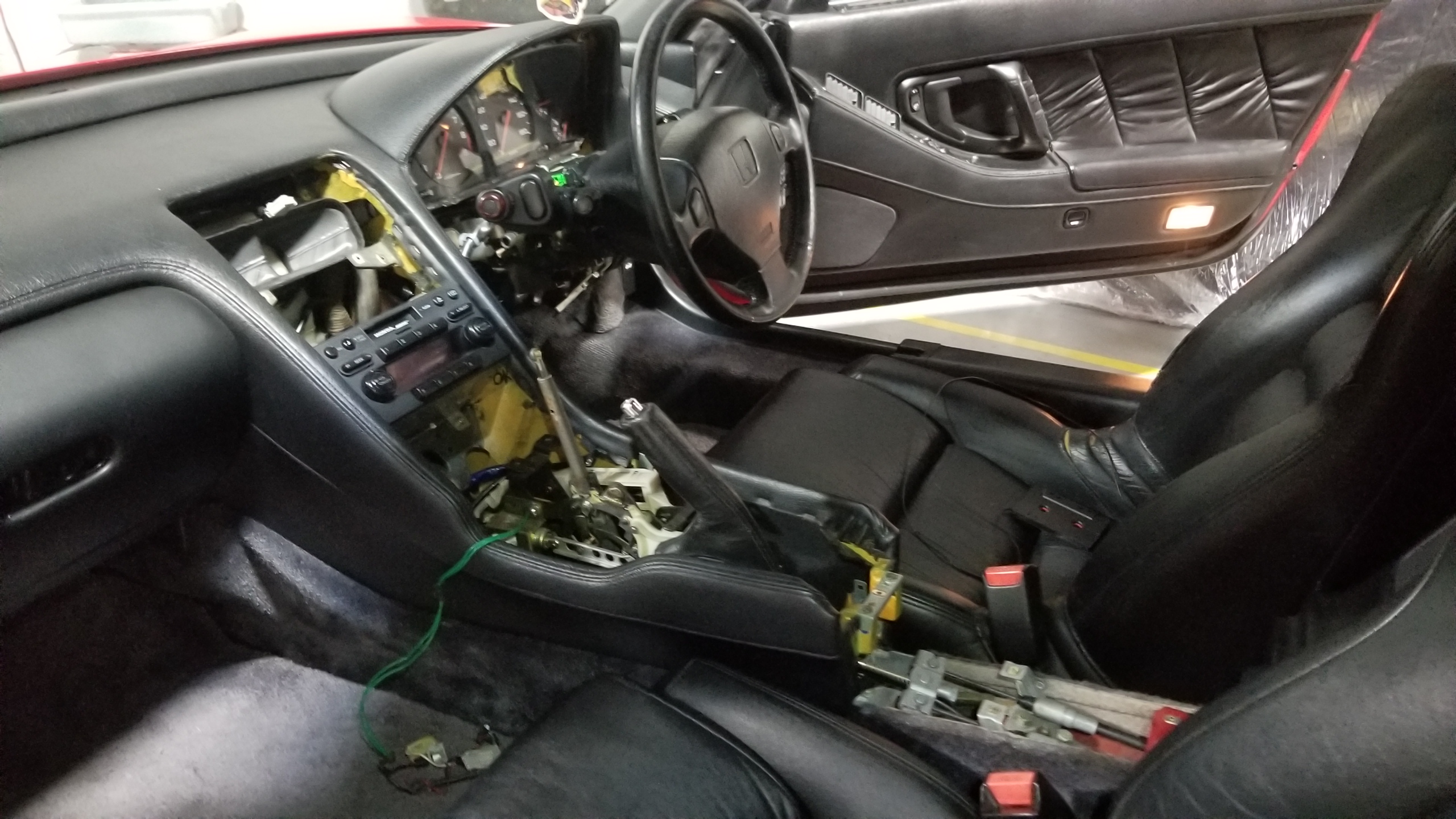
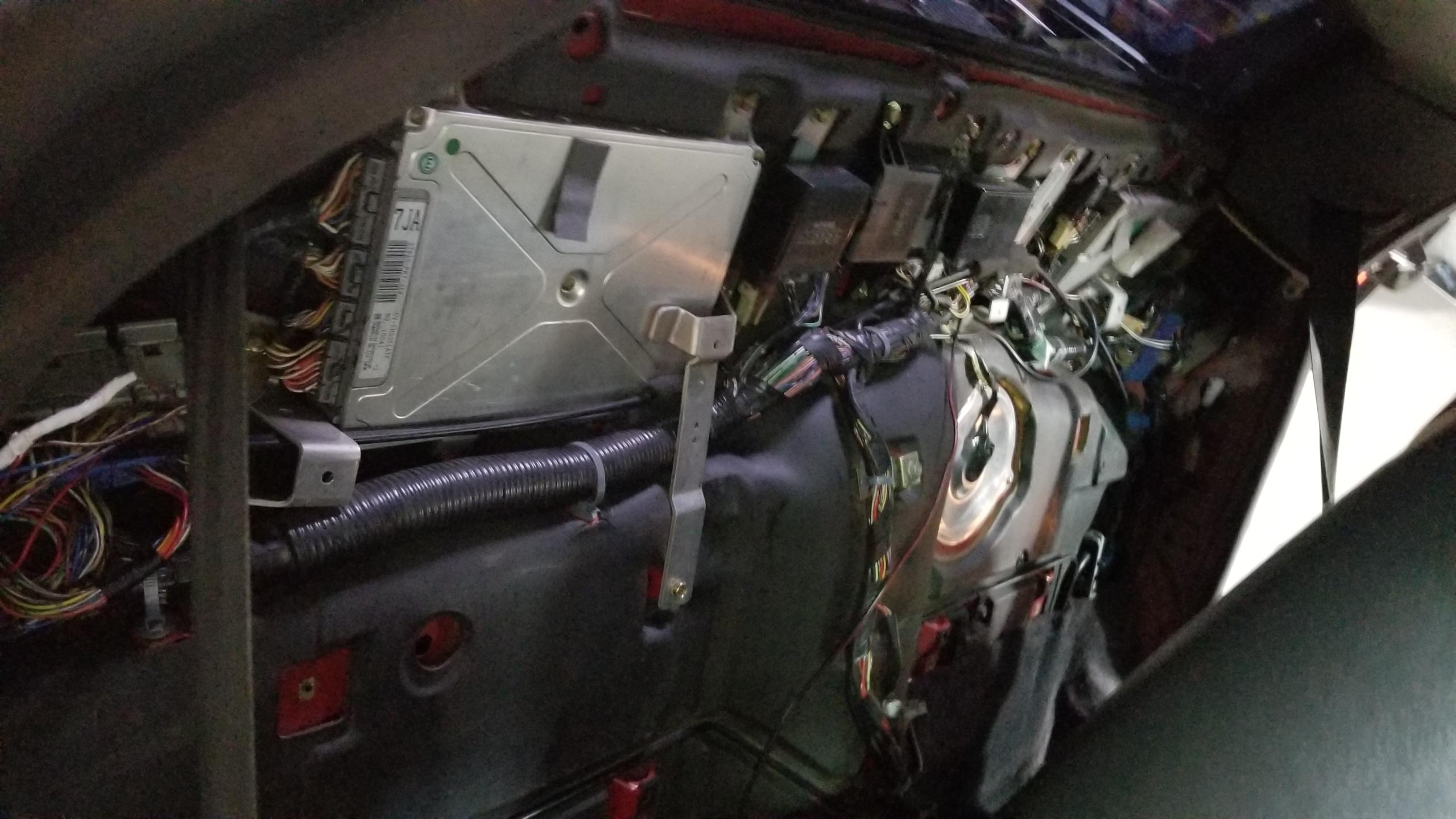
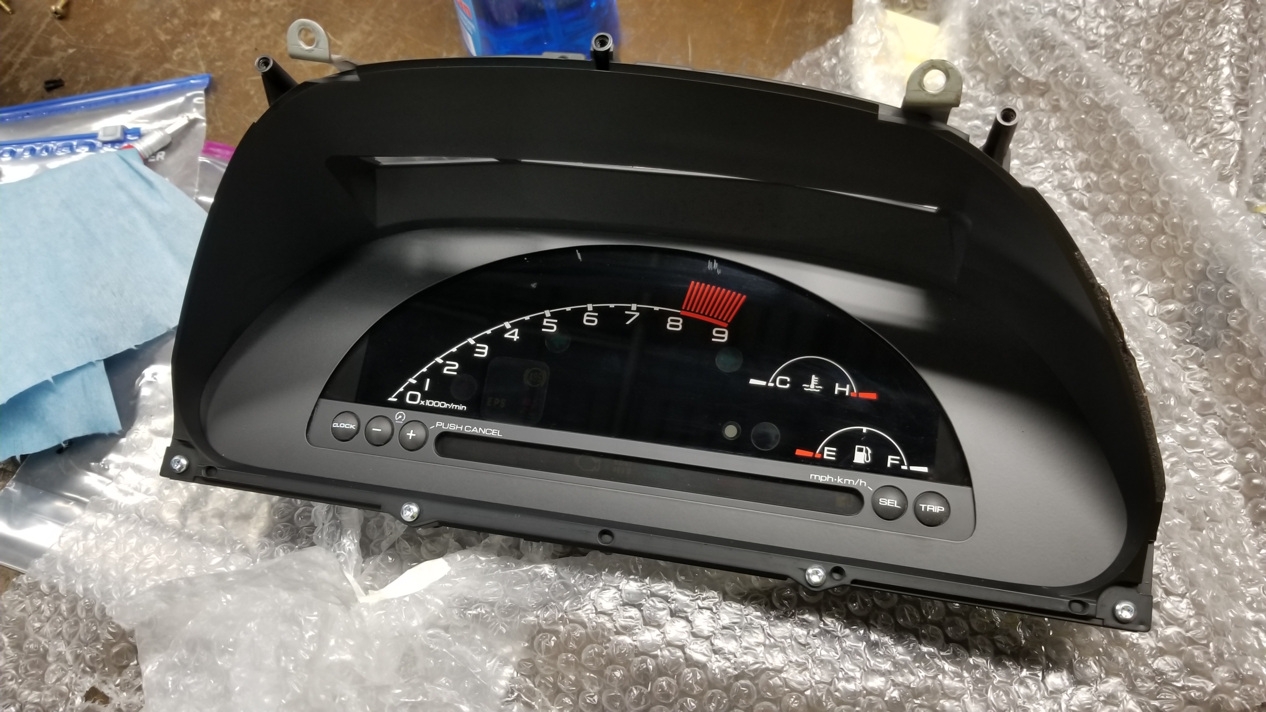
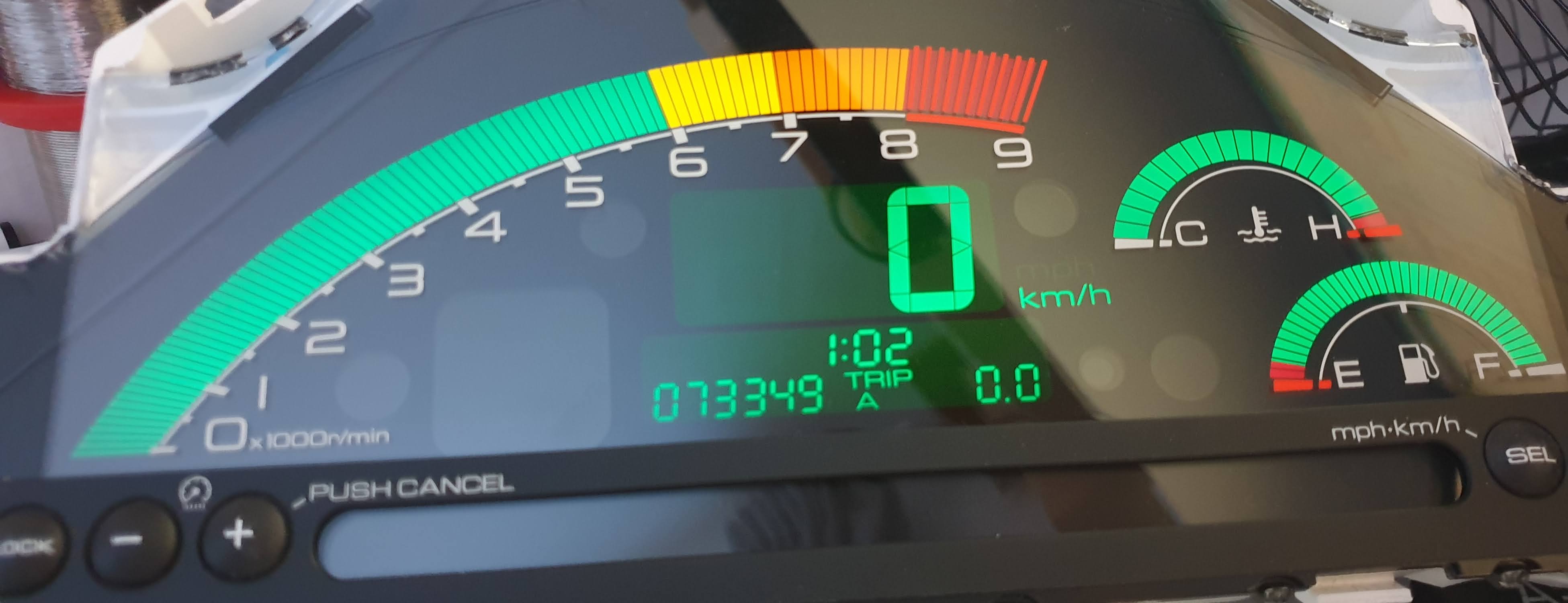
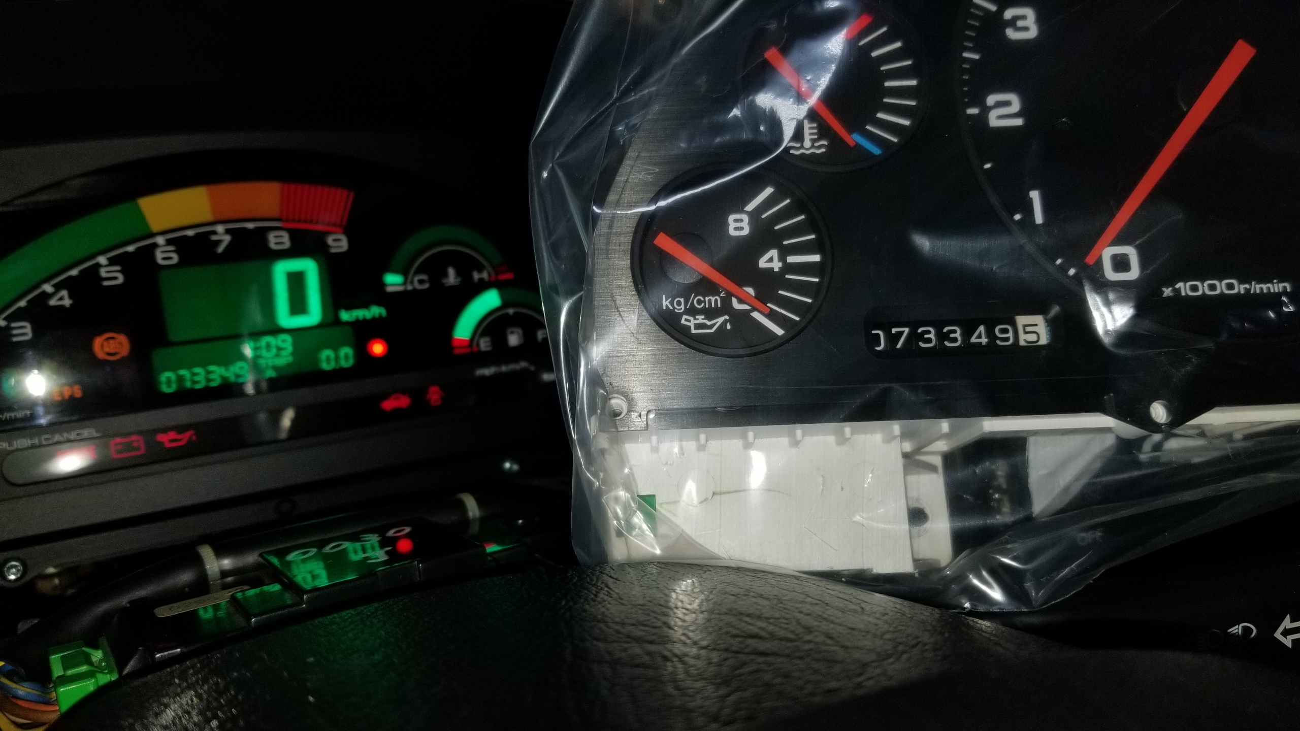
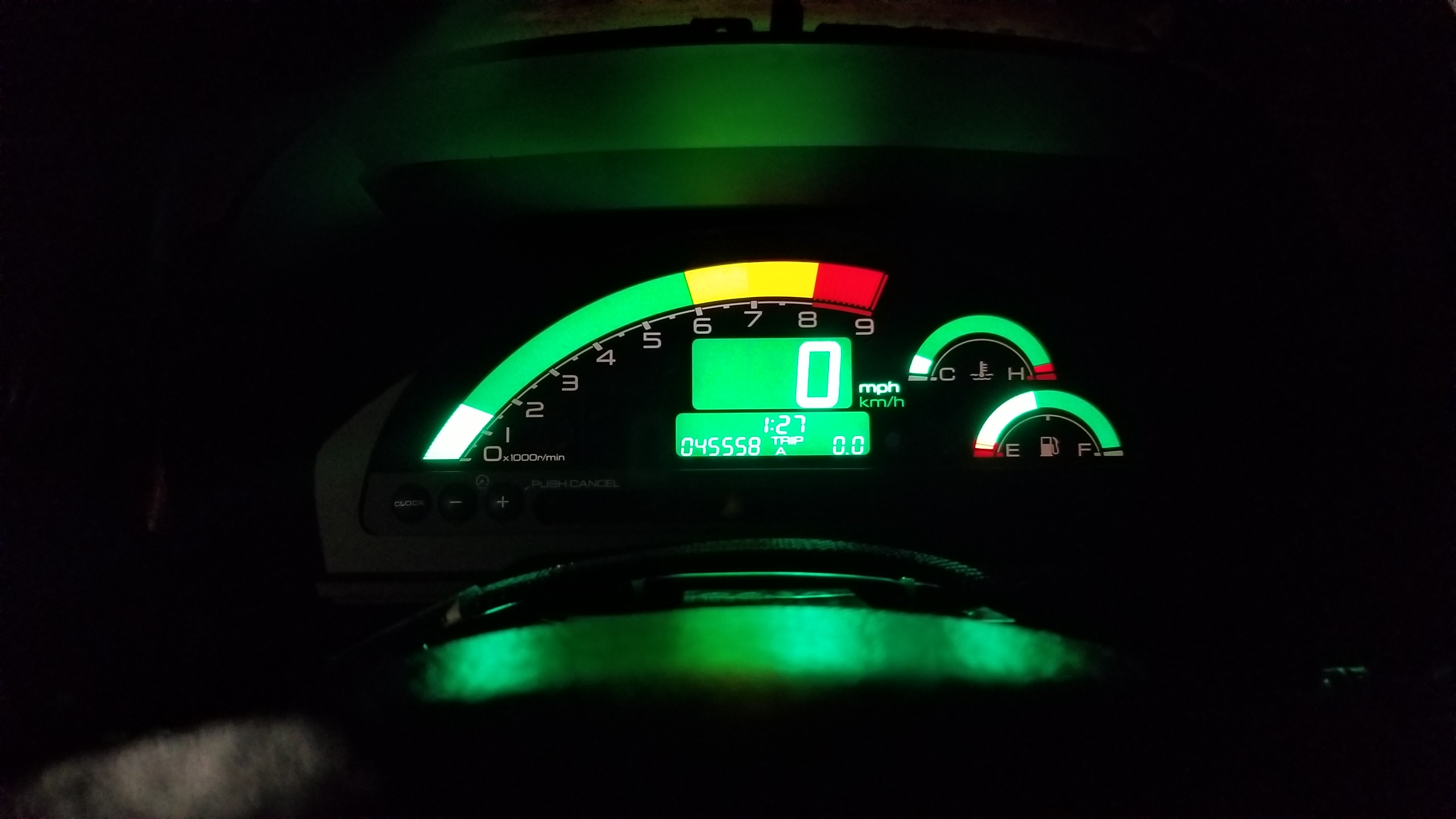
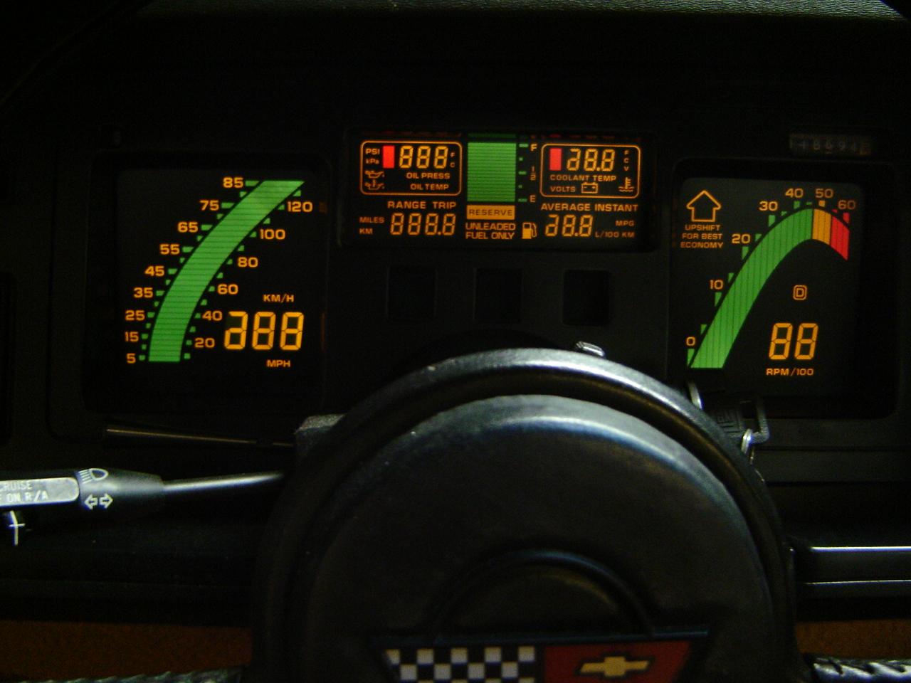
Day 1 is interior focused. Pedal box and wiring. See previous posts for the gauge cluster swap and center console removal.

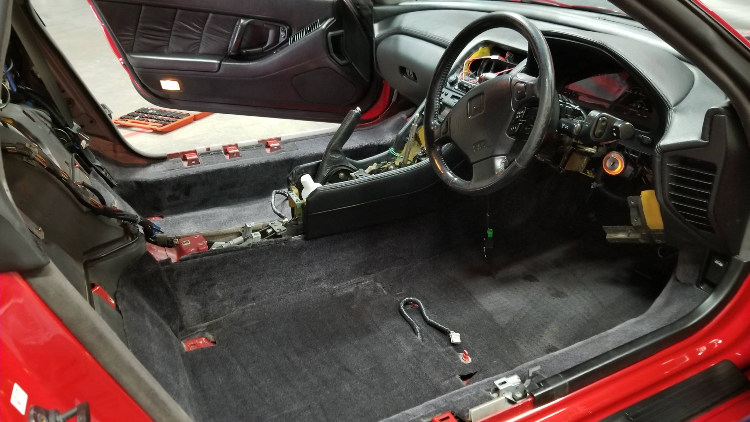
"First" order of business is seat removal. Easy with the instructions in the factory service manual (FSM). Four anchor bolts, one seat belt retainer, one connector each seat. Lift out carefully, they're heavy. I wouldn't dream of doing the next steps without at least the driver's seat out, but just take both out anyways.
QM3tMAy.jpg


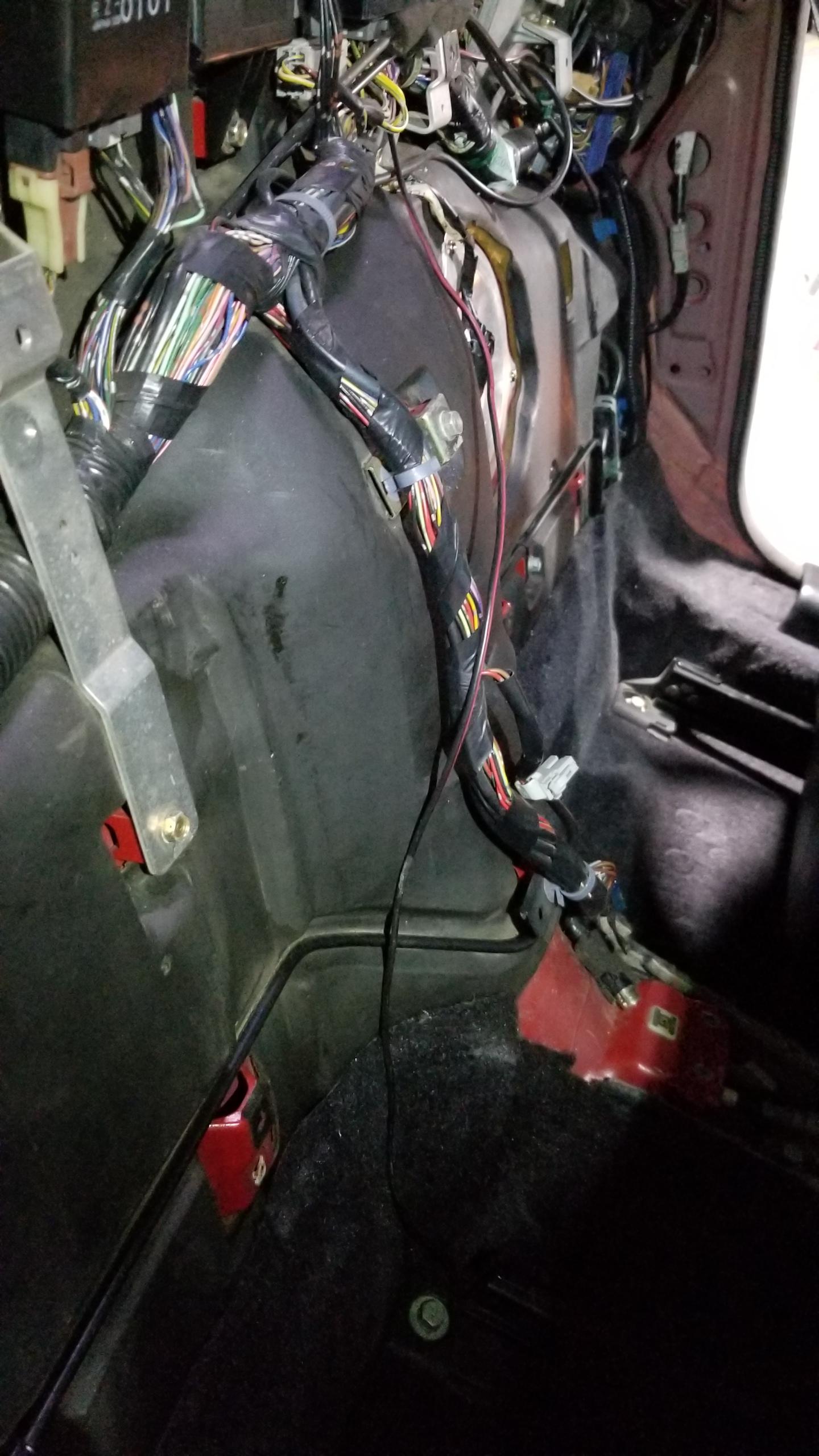
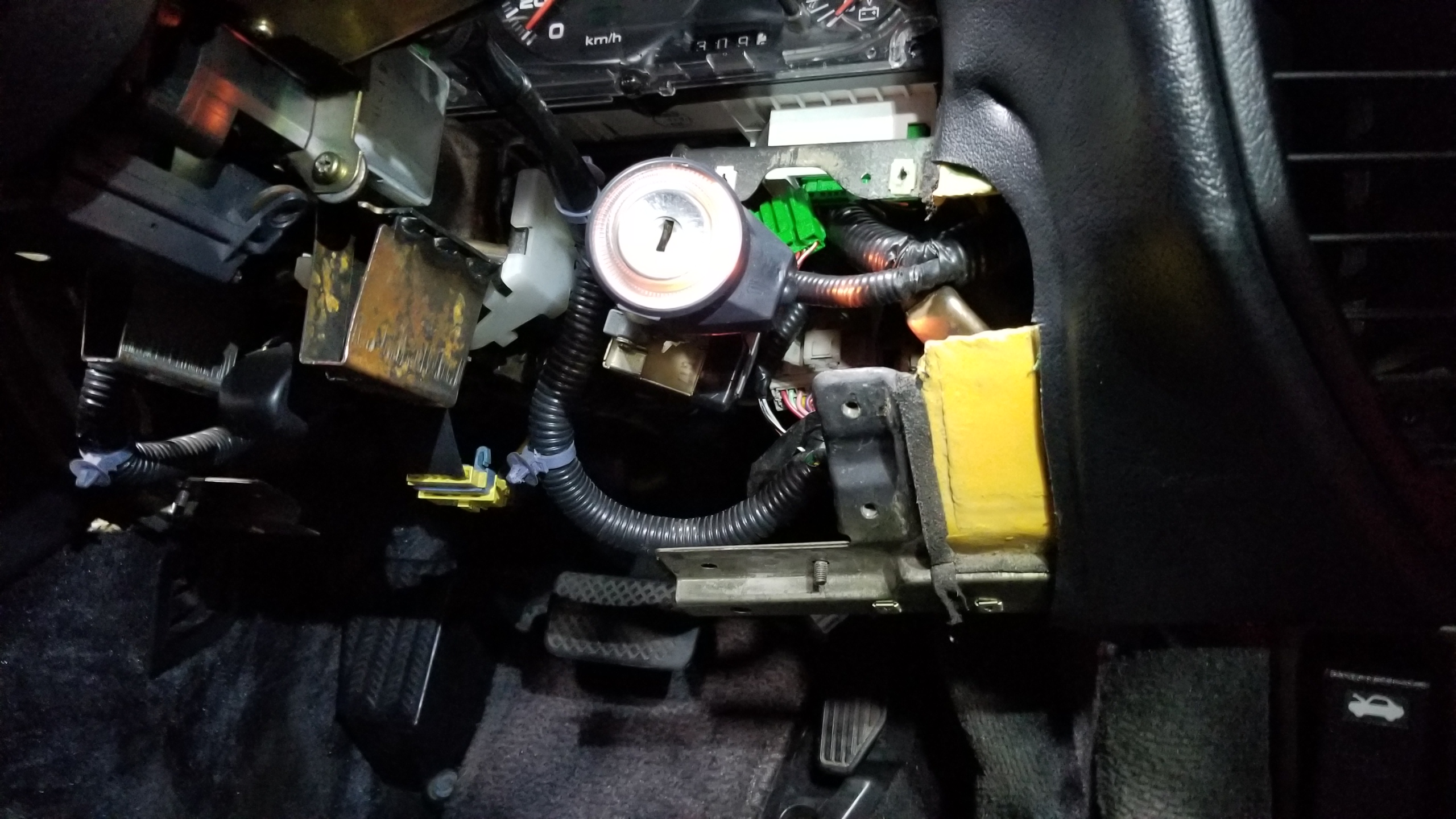
Next, steering column removal. Disconnect the battery. Disconnect a bunch of connectors for the ignition switch, combination switches, SRS, whatever else is attached to the column BEFORE taking the mount bolts off to avoid ripping out wires.

Two bolts on the U-joint, two on a U-bracket, and two more nuts towards the top and the column comes right out. While you're on your back getting the last bolt out, it would be best to have a helper lift out the column from above, it's also heavy.

You can see the right part of the lower dash already broken off from some previous work. I'll have to glue it back in place later on. Maybe JB weld or something would work best.
x06jH86.jpg


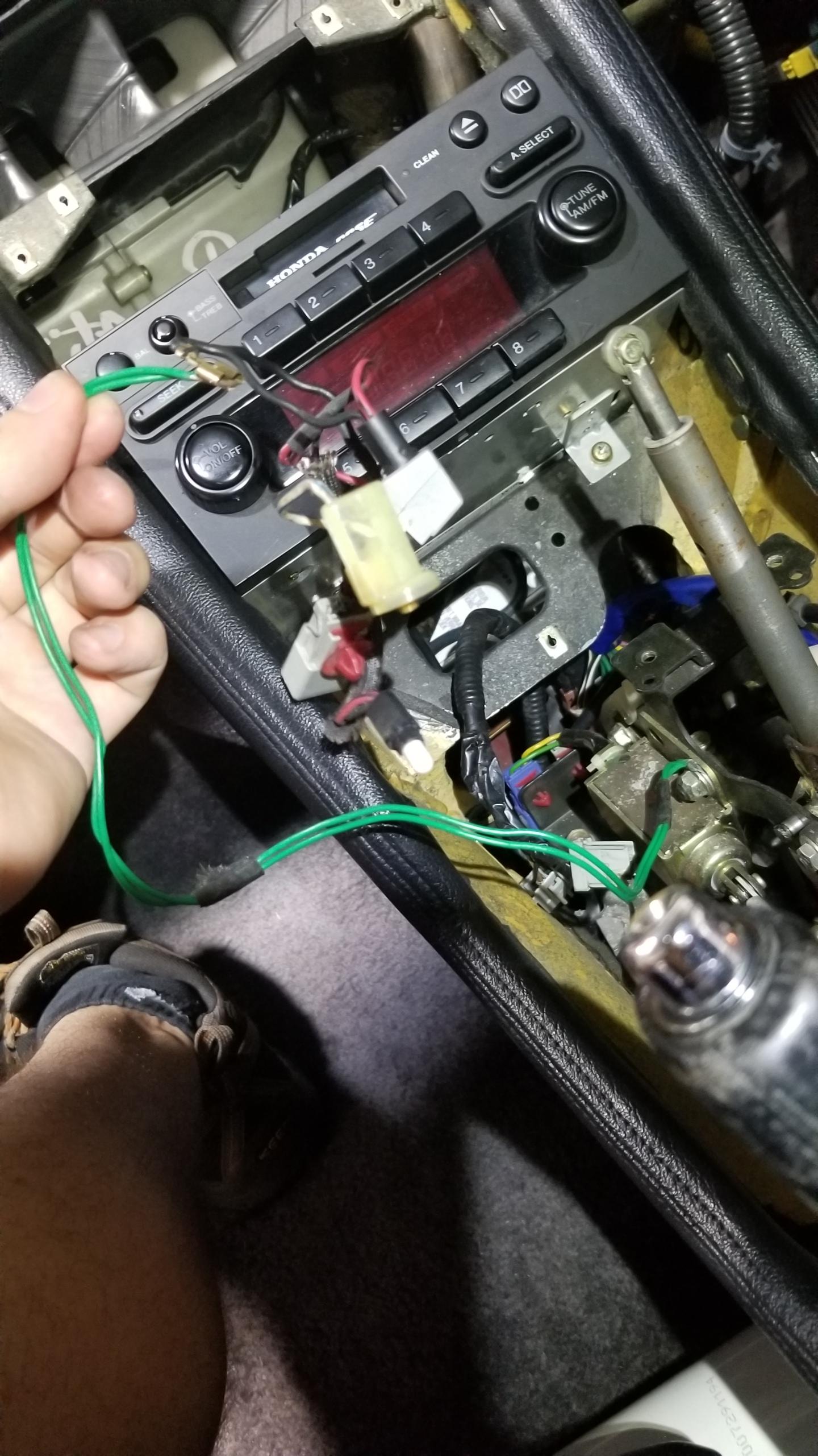
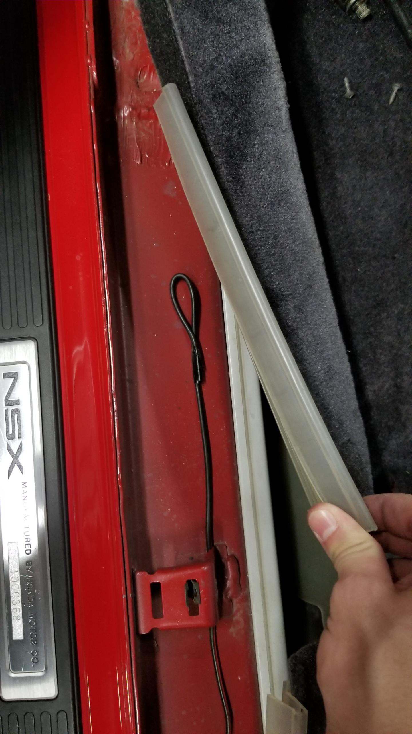
Here's where the other end of that random wire from my last post ended. Just a random unused wire. I took it out and threw it away.
BaD3Vq4.jpg


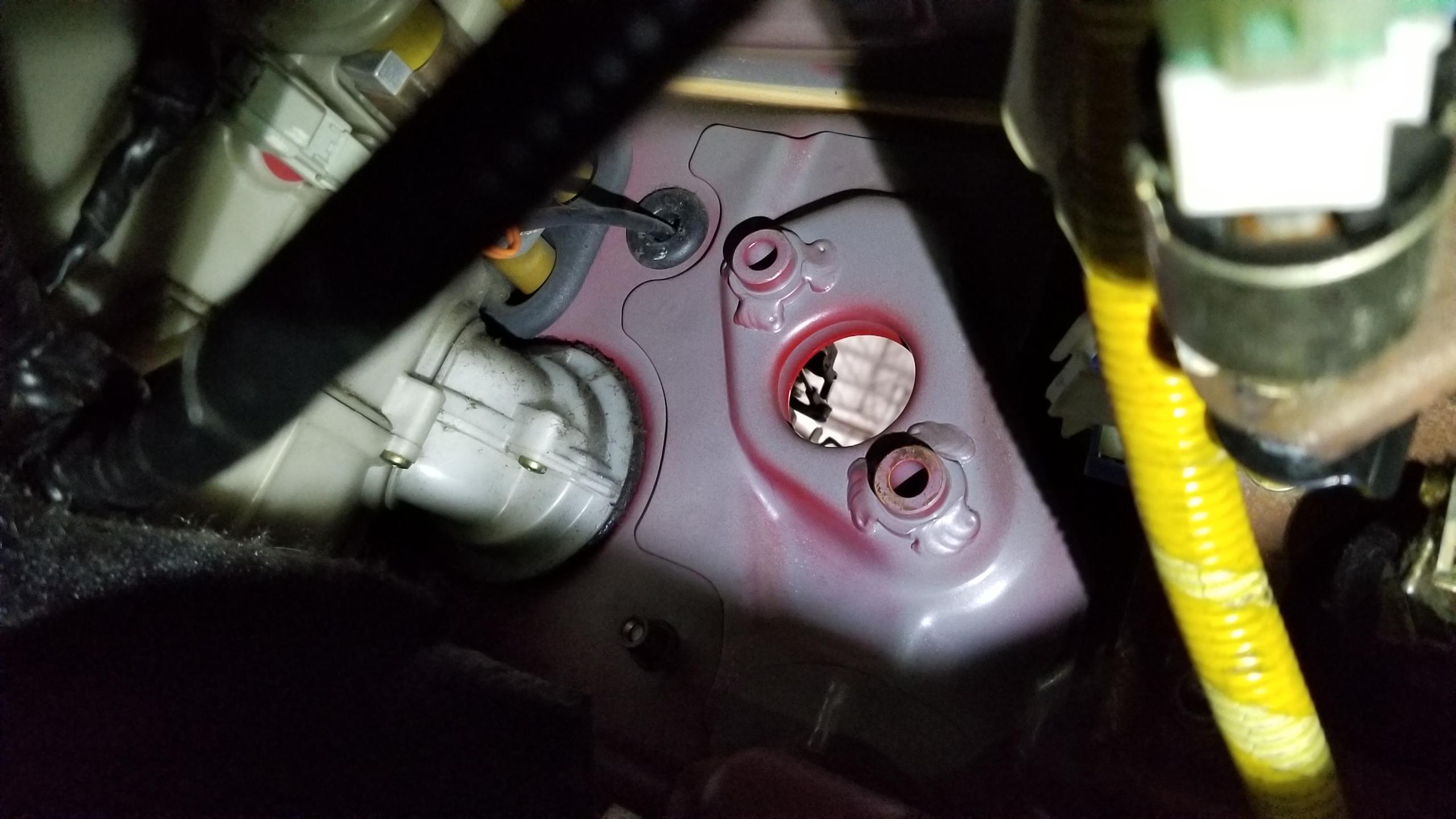
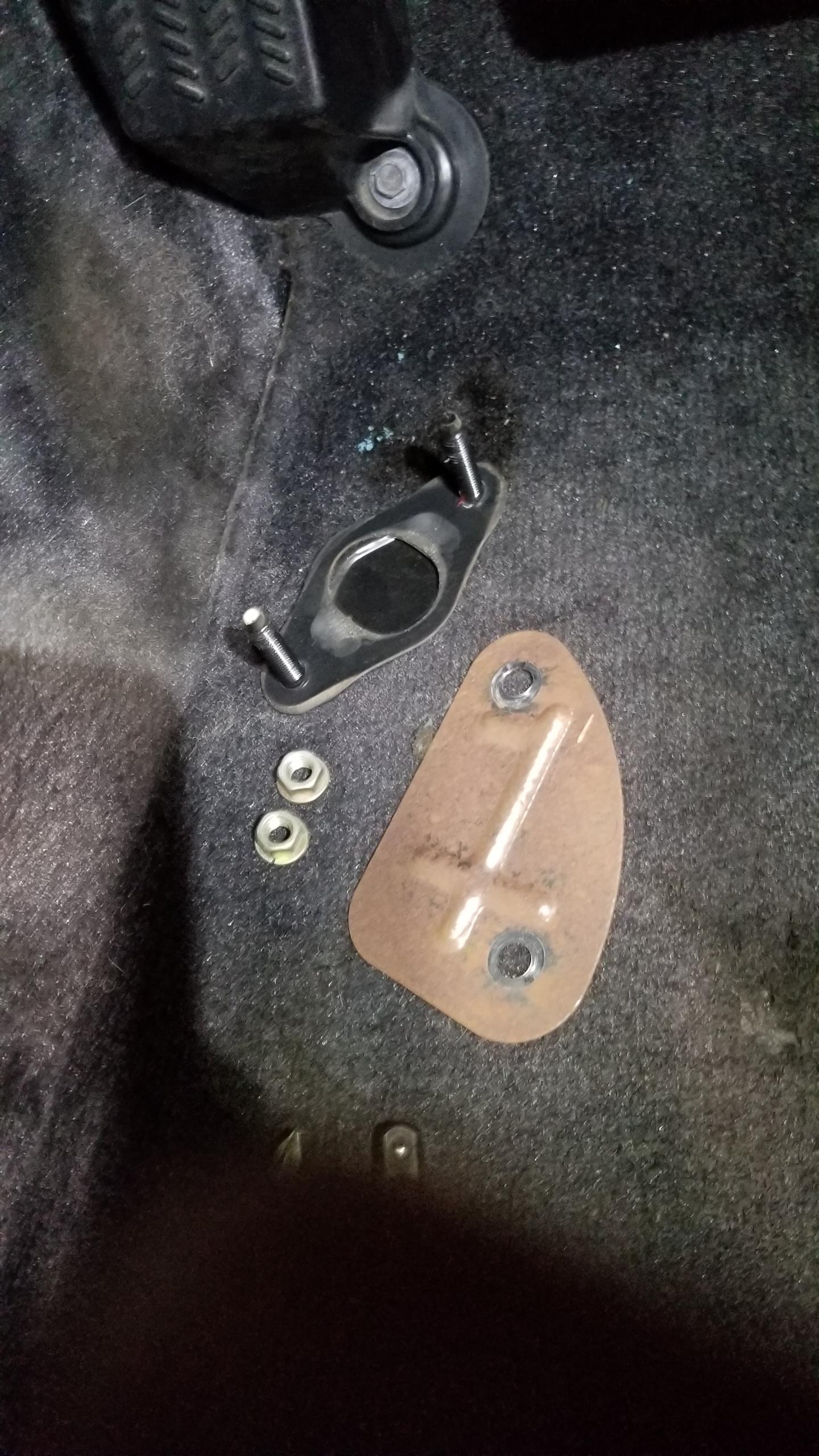
Beginning the clutch pedal install. Here's where the blanking plate for the master cylinder was. Two nuts removed and punch out the black seal on the frunk side. EZ
RyL7jC3.jpg


Blanking plate and seal w/studs. You can reuse the nuts for the master cylinder if you want.
X6W58b4.jpg


Test fitting the pedal & bracket. Unfortunately it looks like the vestigial arm on the top for the unused second clutch switch hits the body at the top, so I wanted to cut it off to get more room.
8gQ7EFc.jpg


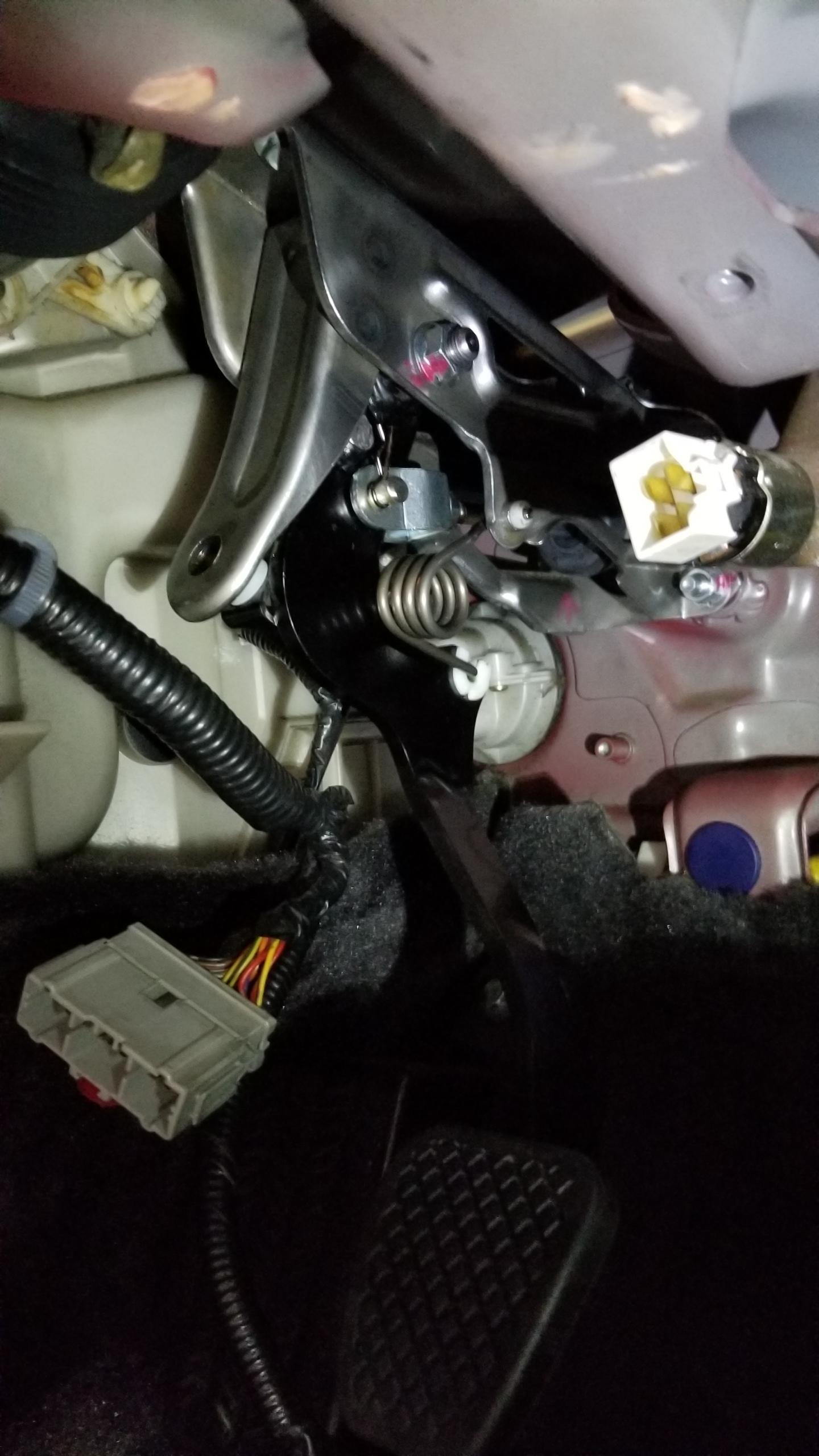
Clutch pedal modified and spring installed. The spring can go on with no compression needed with the pedal all the way back. Friend and I fucked around with compressing the spring to get it in place for way too long before we figured out how to do it properly. Also, we got confused on the direction of the spring since there's no resistance on the pedal, so when you push it back, it springs back and gets stuck down. The clutch master is what provides the hydraulic pressure to push the pedal back in place so the pedal won't feel right until the lines are complete. TIL.
79AAWpT.jpg


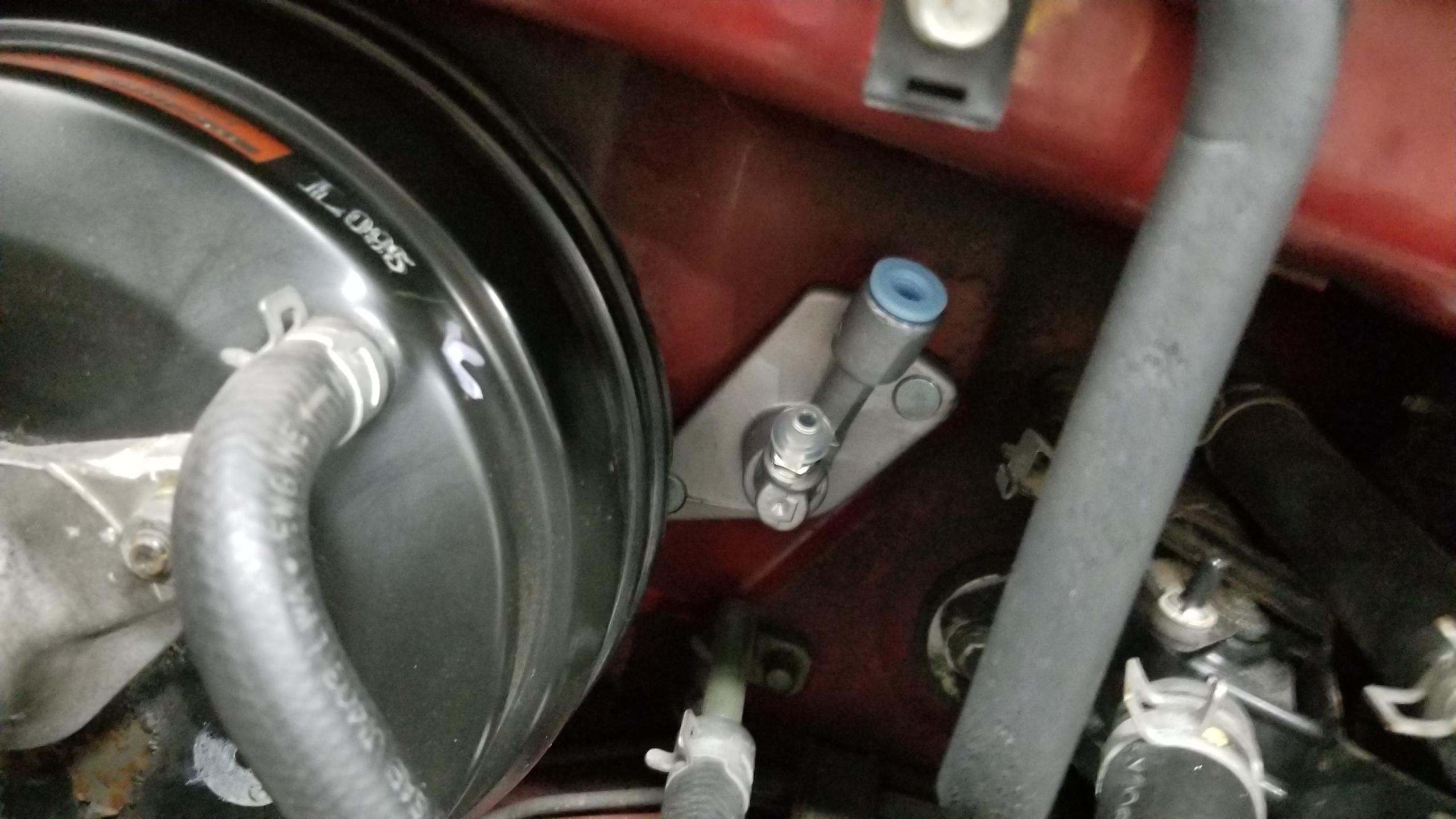
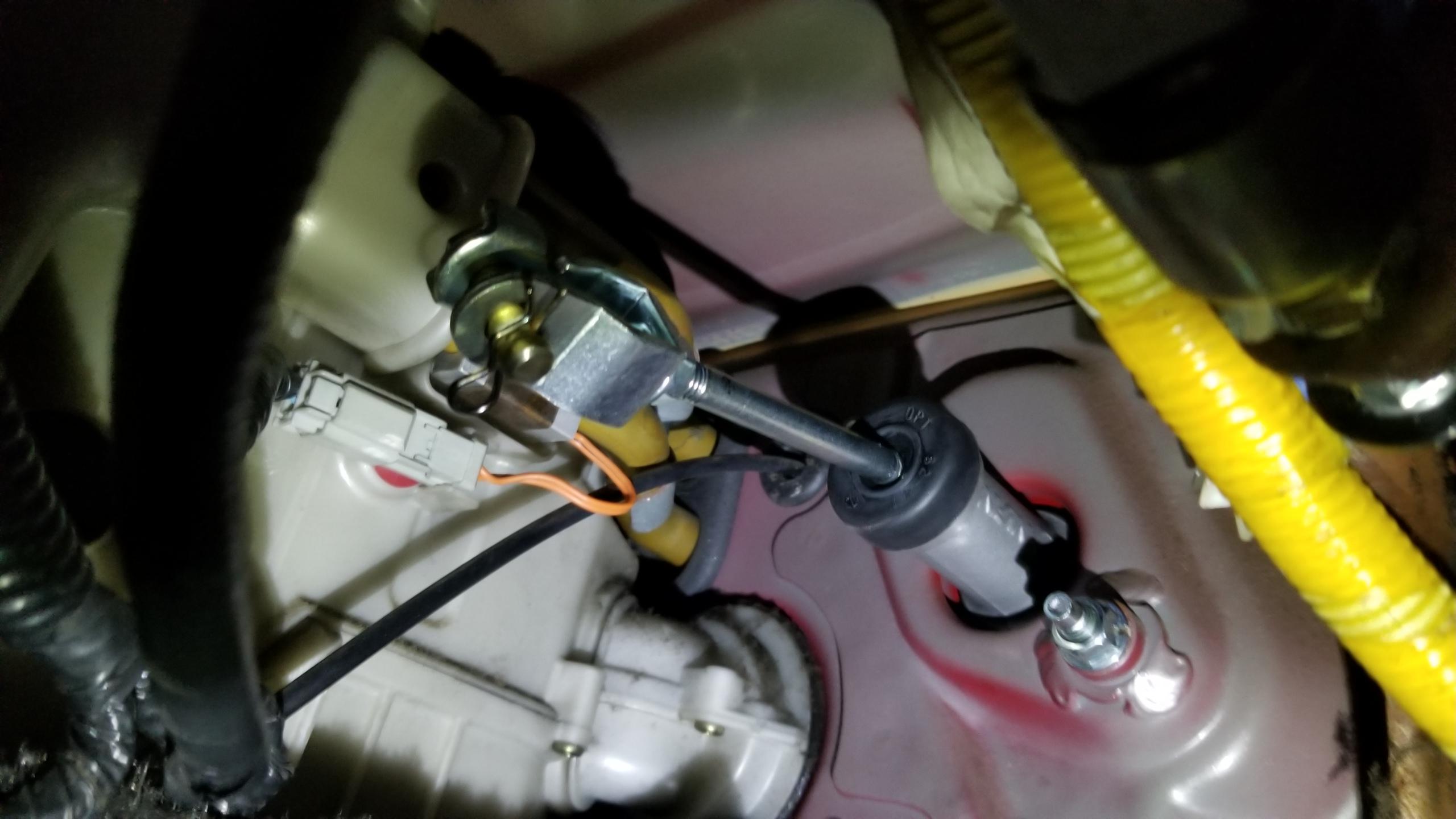
Clutch master pushed into place from the frunk. Simple. There's a rubber gasket that goes in between the master and the body, it's not included with the master.
hPmbrLq.jpg


Here's what it looks like from inside. The nuts are supposed to go on after the bracket is in place, FYI. The pin & spring on the end will attach to the clutch pedal.
D42B9Dm.jpg


Pedal & bracket installed. Not too bad, two nuts on the master studs and one bolt at the top of the bracket into the upper dash. All factory bolt locations. Blue clutch stopped pad installed in the background. I haven't installed the clutch switch yet in the picture.
TWJB2xo.jpg


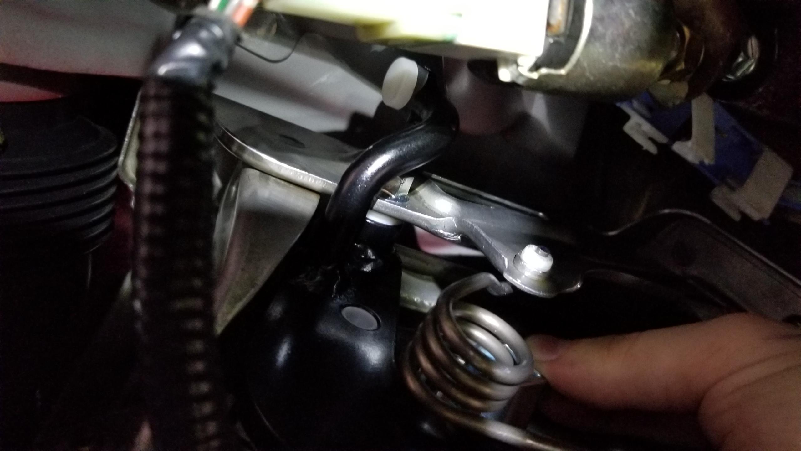
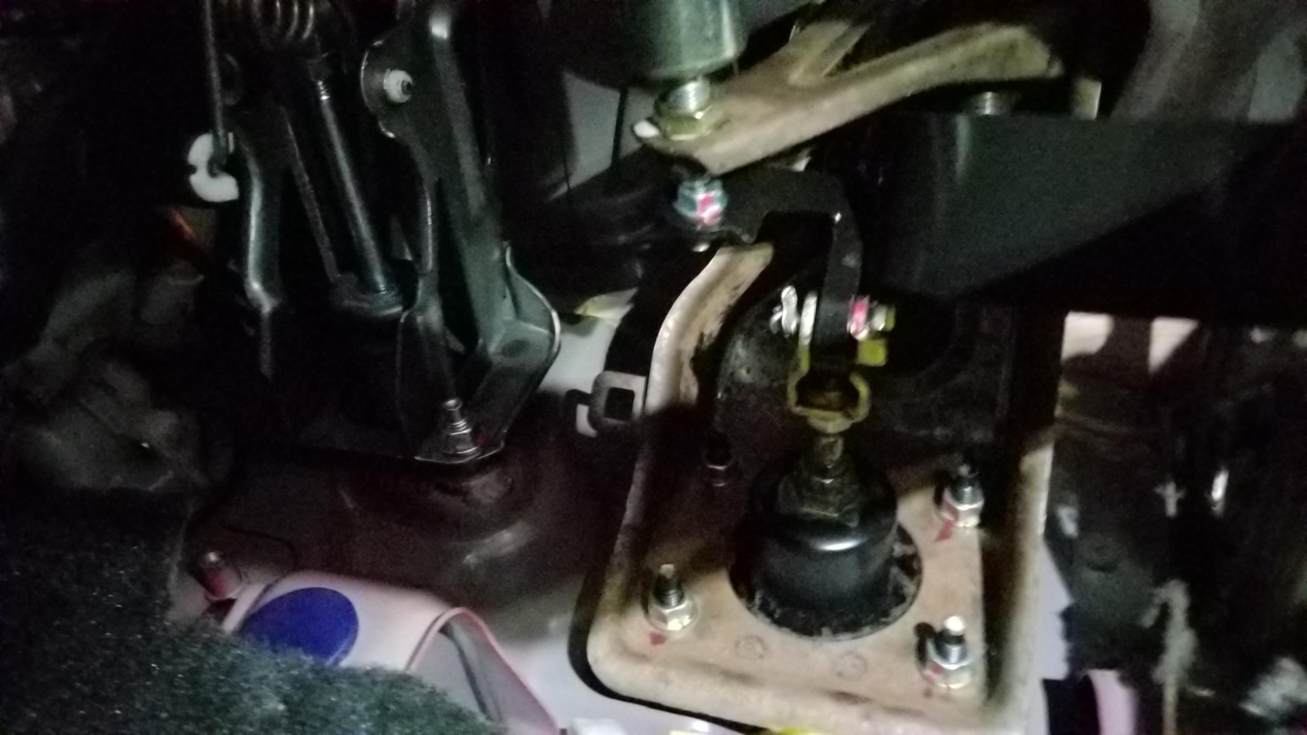
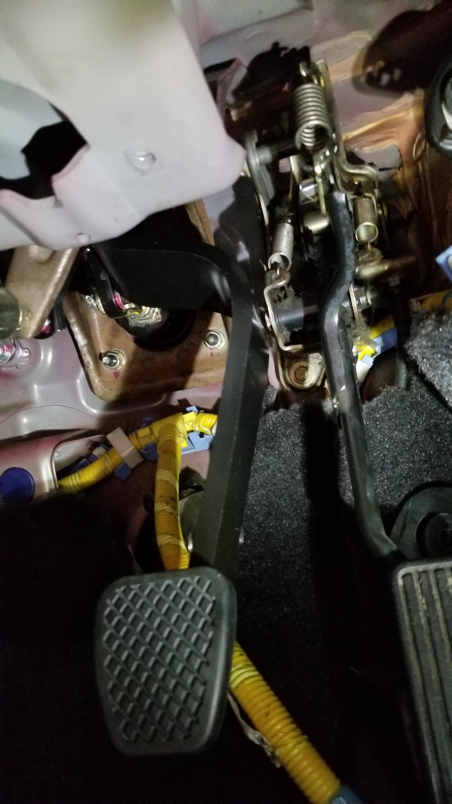
Now for the worst part so far by a long shot, removing the A/T brake pedal to replace it with the M/T version. This pic is actually after the install but I didn't get one of before. Basically, you can't remove the bracket without removing the master cylinder completely which would suck. You have to pull the master slightly to get the studs out of the bracket to get enough room to take out the through-bolt holding the pedal in, and the bolt was on super tight. Then there's a spring from the bracket to the pedal that has to be removed. This took like an hour just to take the pedal out. Suuuuucks.
6lw3Cp0.jpg


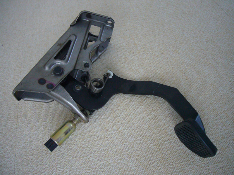
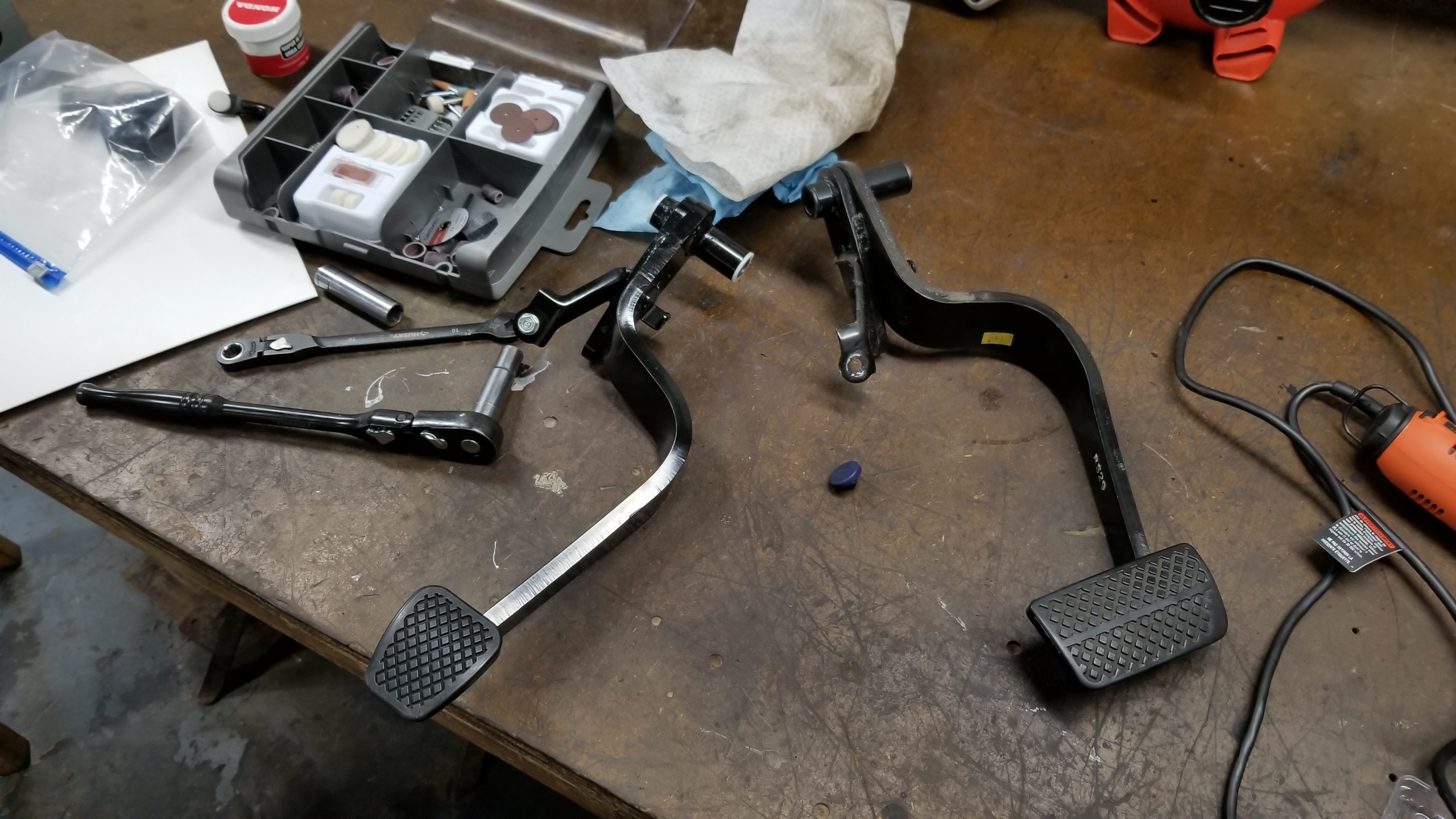
New and old brake pedal. Getting to this point was a massive pain in the ass. (I'm sure you'll see more of those before this is over). You can re-use the pedal collar for the new pedal, same size. I transferred over the bolt I used for the brake switch stopper.
ts8O8Qi.jpg


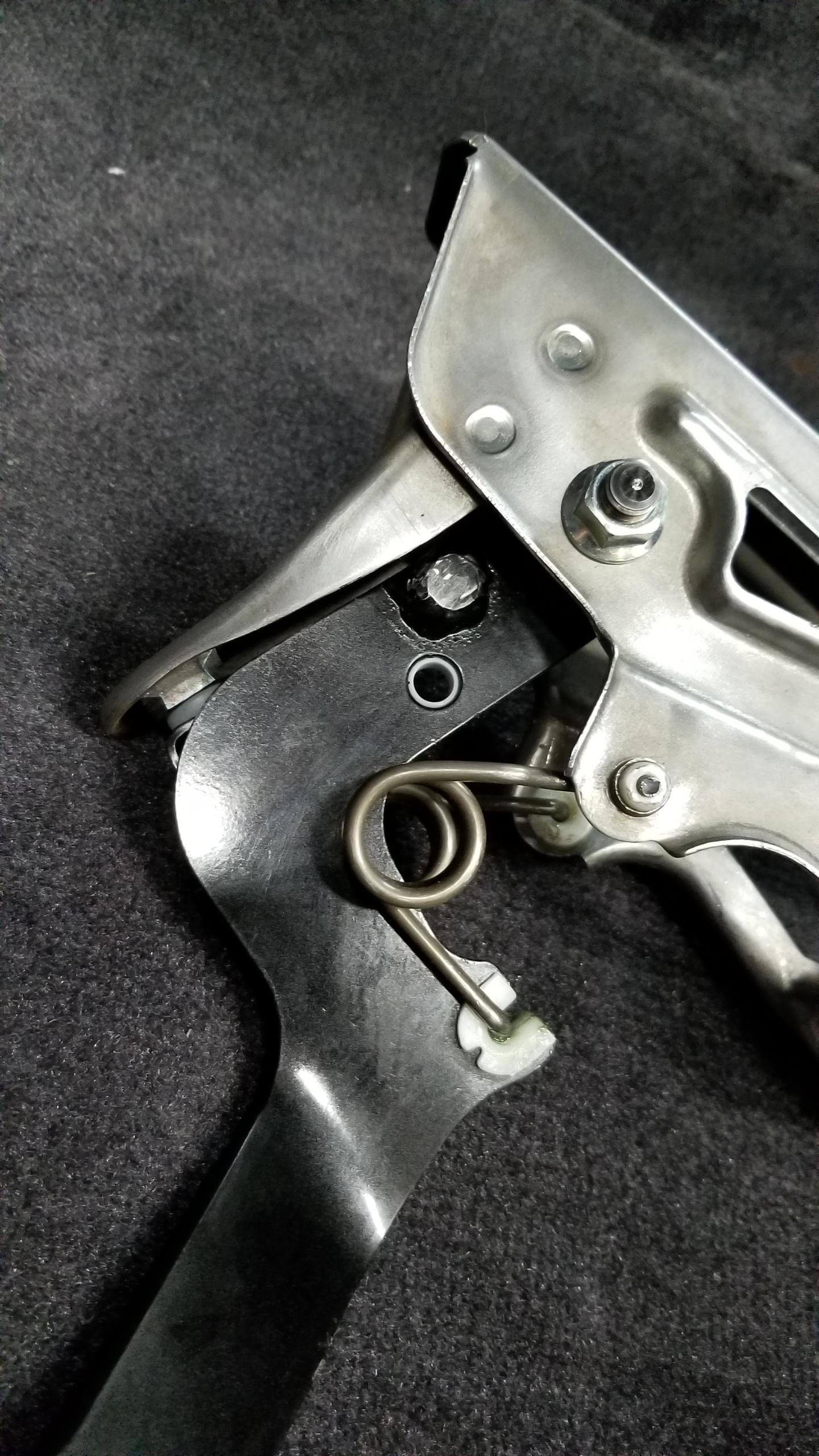
New pedal installed. Putting it in is just as shitty as taking it off. The worst part is getting the spring back onto the new pedal, I had to use very long articulated needle nose pliers to grip the end of the spring and thread the needle onto the new pedal which took almost an hour by itself. Ultimately I'd love to take the whole brake pedal bracket out in the first place but didn't want to mess with the master cylinder and remove it or bleed brake fluid. Oh well, it's installed now.
VKy7Jqm.jpg


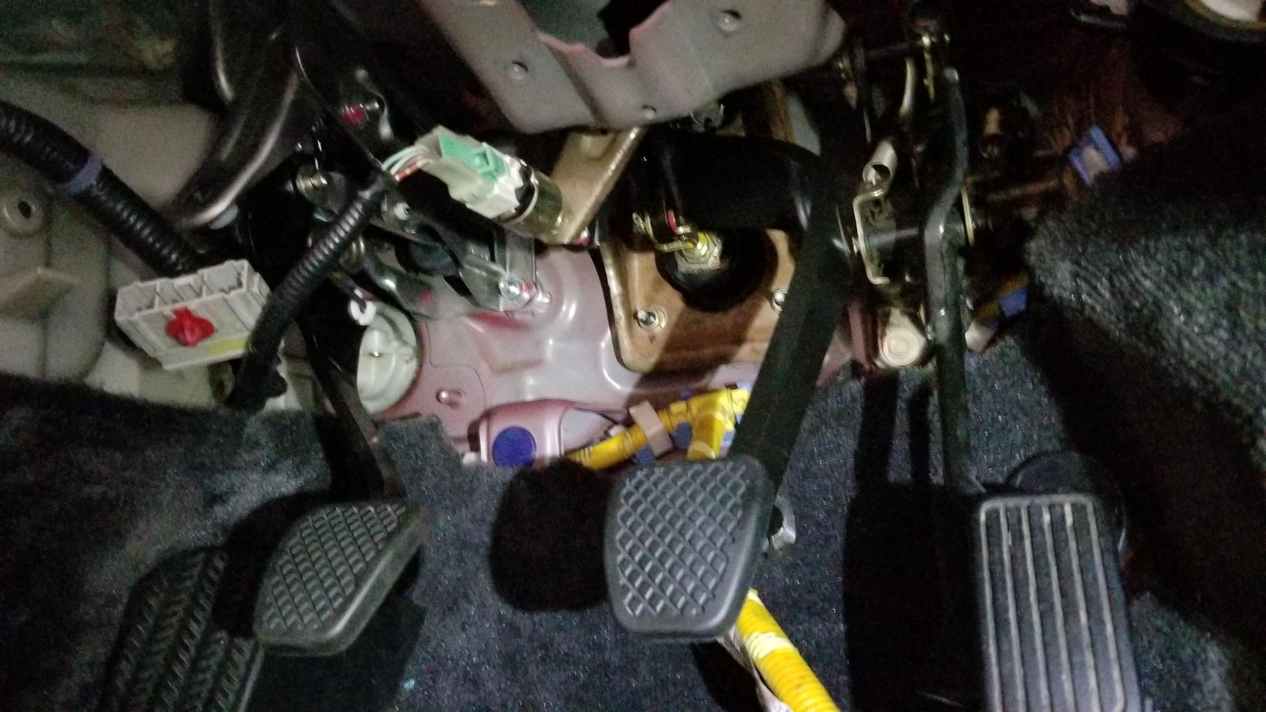
Three happy pedals. I have not adjusted the free play for the clutch or brake pedals yet but will do that towards the end of the project. I don't believe the brake should need to be adjusted. (or rather, I hope not).
ZXL9YvB.jpg


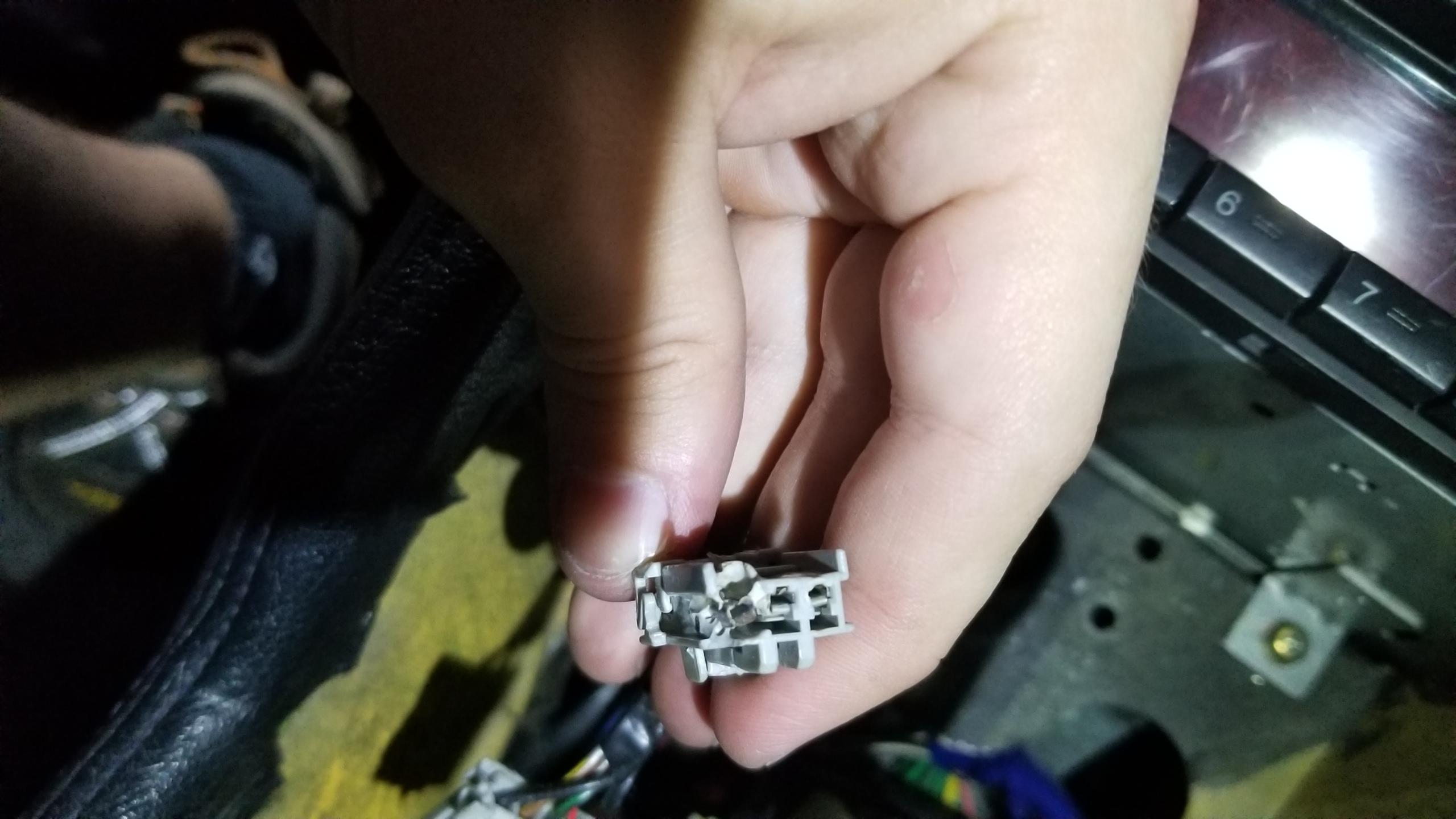
Time for some wiring. I took some time and fixed the cigar lighter harness from my previous post since it was messed up. I used an OEM 3P terminal, cut off the old one, and crimped on the new terminal. Good as new.
wfSrPp9.jpg


Fixed the male side of the harness with a new connector and terminals. Two old ones I cut off on the bottom. Hopefully there's nothing else wrong with the circuit besides this.
2ChEtbI.jpg


First major patch harness in progress. I'd never crimped my own terminals or made a harness before so this is a learning experience. I practiced with a few terminals before doing these final connections. I'll post my modifications of the FancyCraft wiring diagrams here (https://fancy-craft.firebaseapp.com/NSX/report/at-mt/report4.htm) but I need to make some updates from some mistakes with my markups.

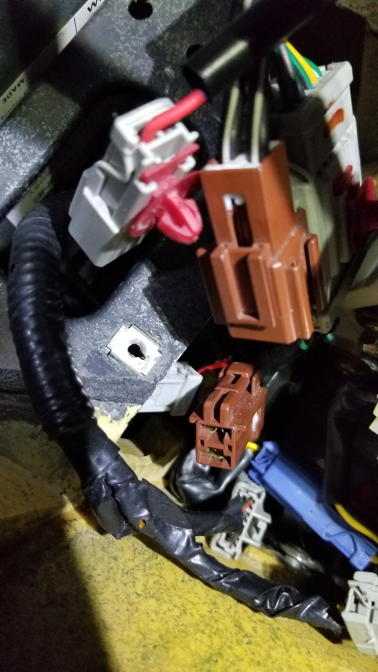
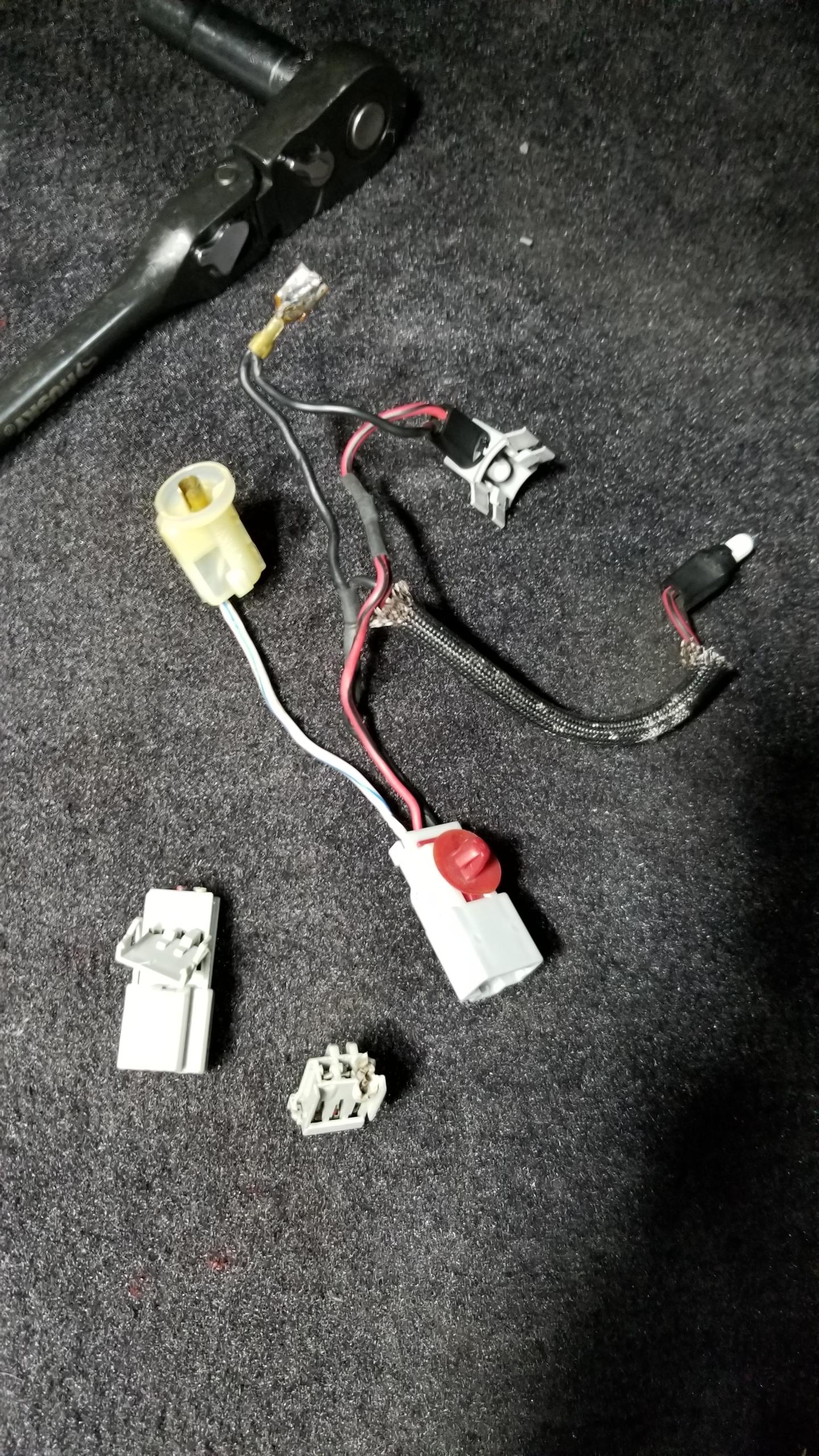
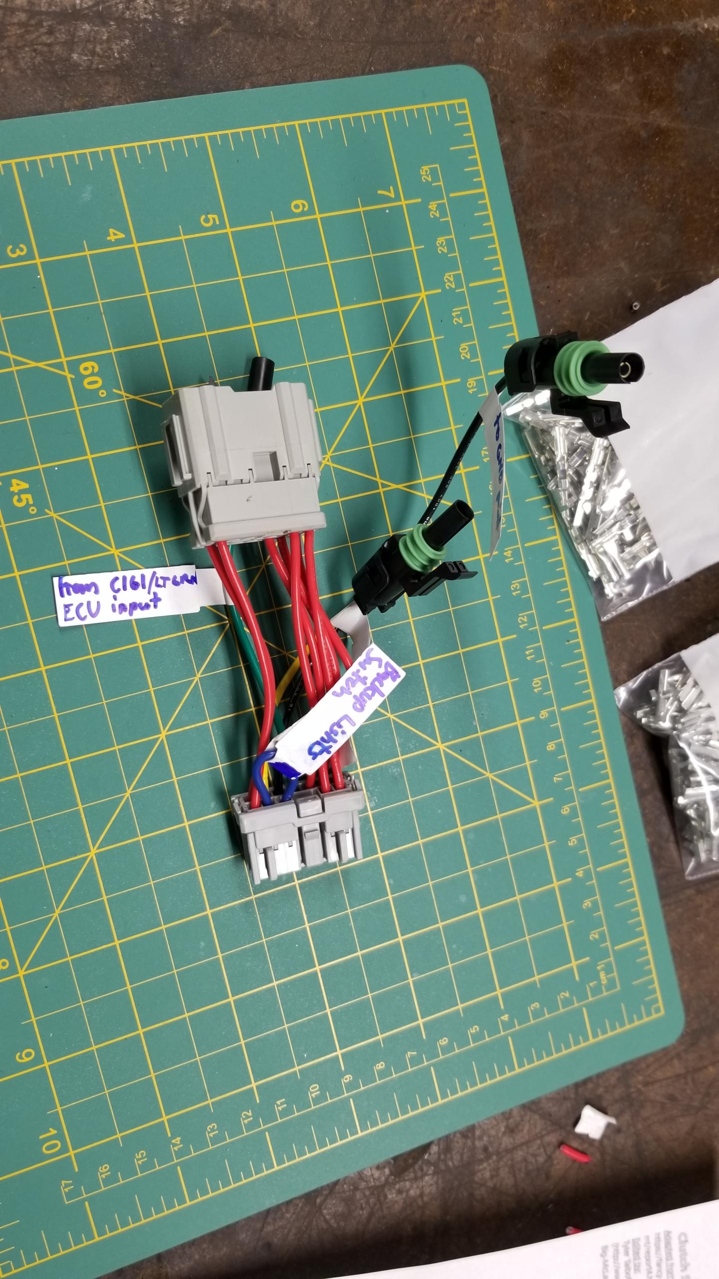
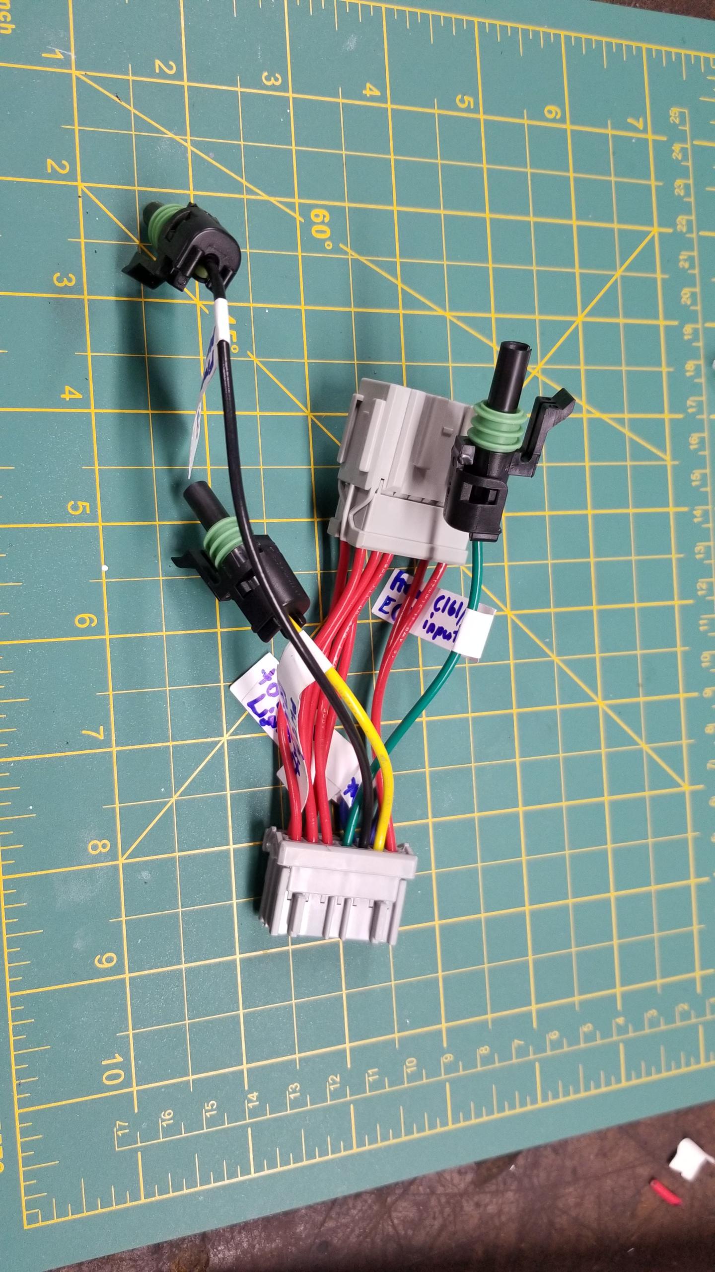
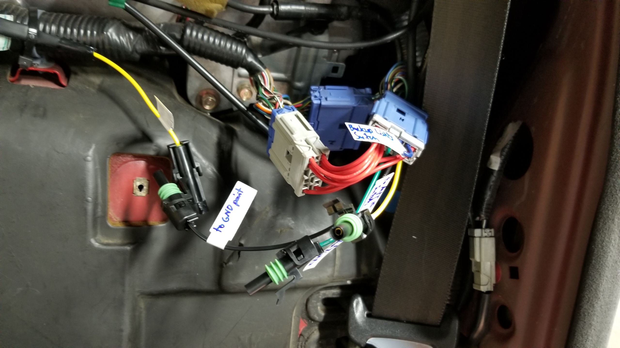
This harness will be for C499 which is on the passenger (left) rear side of the firewall. This will mostly be used to wire in the backup lights and backup light switch and connect it to the YLW power line. The single-pin weatherpack connectors are from another kit I bought, not Honda OEM but work perfectly fine. I didn't have the proper Honda connectors for those lines, these weatherpacks are overkill for these interior harnesses but it's what I had on hand. I also could've used one 3-4P connector instead of 3 separate connectors but this was more of an iterative process than something I planned.
rohLJYP.jpg


Other side of the patch harness. Red wires just connect the original male to female pins to keep the same function. Yellow wire sends power to the backup lights. This connects to the yellow wire on C425 on the shift console switch, which normally sends power to the shifter itself but that function is no longer needed, so I re-routed the power from the connector to the lights instead.

Black wire is to ground for the ECU neutral switch input. Green connects the ECU neutral switch input to the M/T neutral switch on the trans. The blue jumper wire ties together the backup lights to the backup light switch on the trans. I think this should work well.
Oa1wLeF.jpg


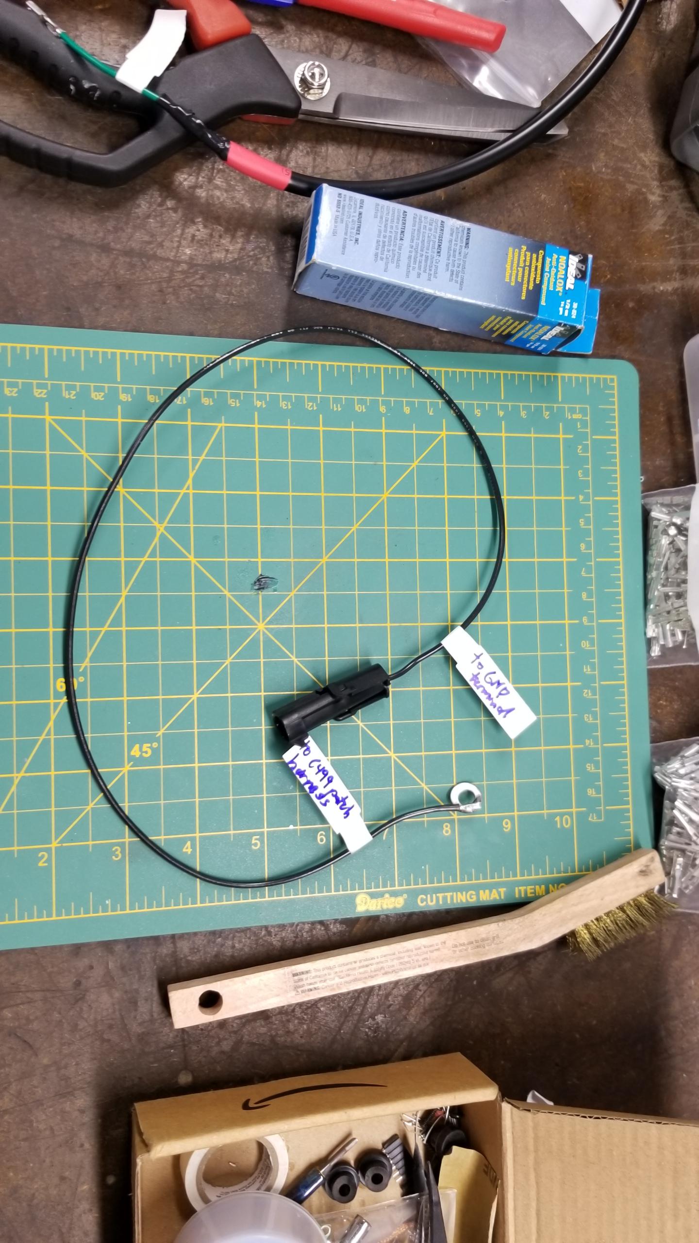
Here's the other end of the ground harness for the neutral switch. It connects to a factory ground in the middle of the firewall.
gOuh793.jpg


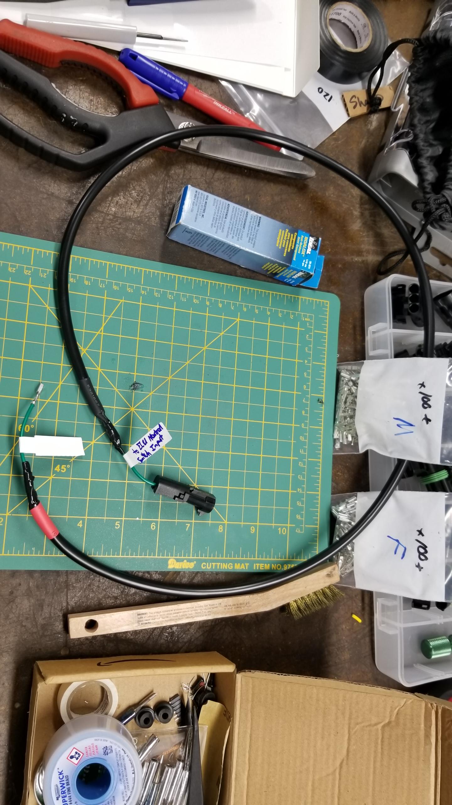
Here's the "harness" for the ECU neutral switch. I could use normal connectors on both ends instead of an OEM female terminal on one end but this will work fine. (i.e. I'm not that good at thinking ahead).
DIRsj0F.jpg


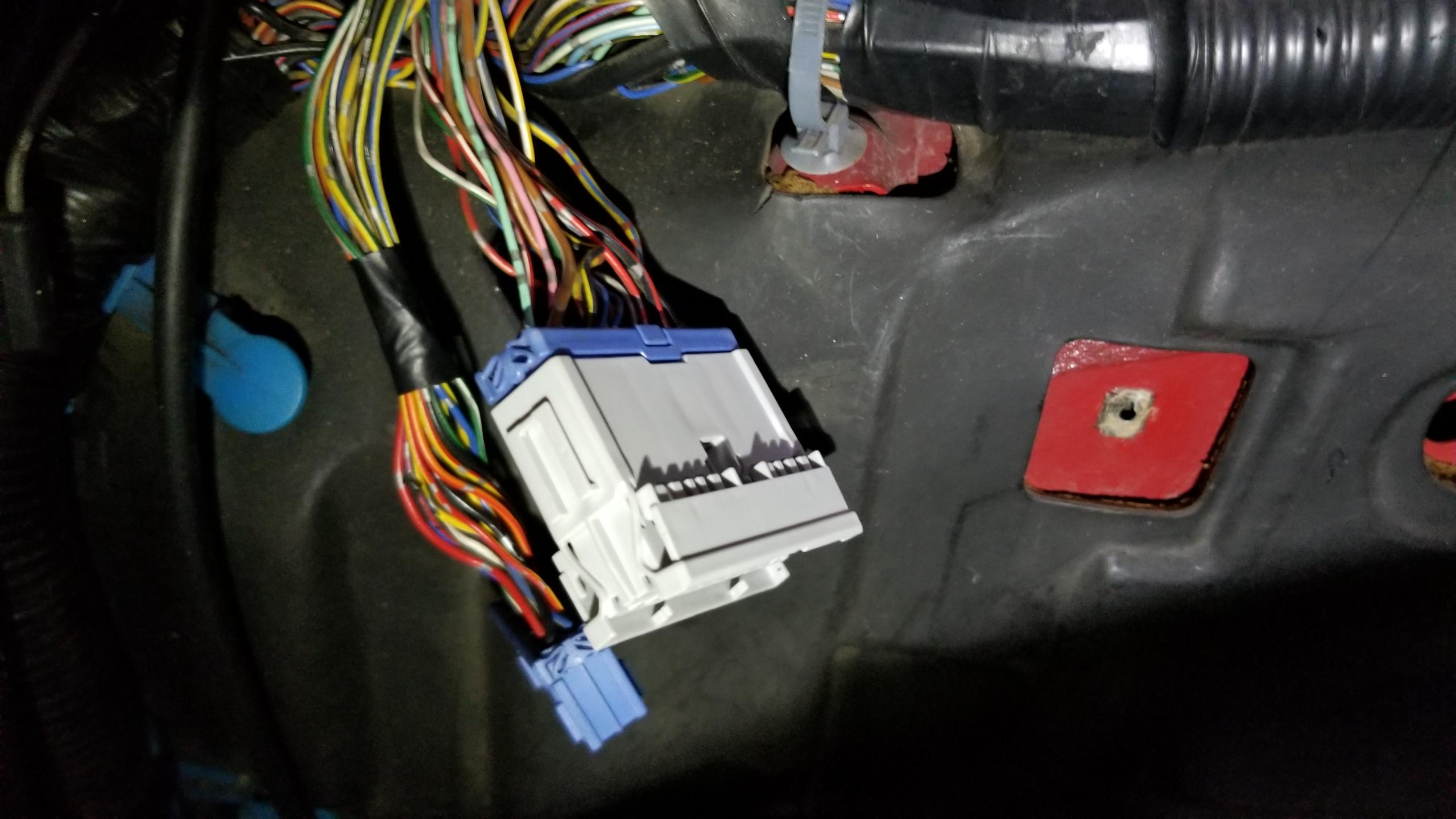
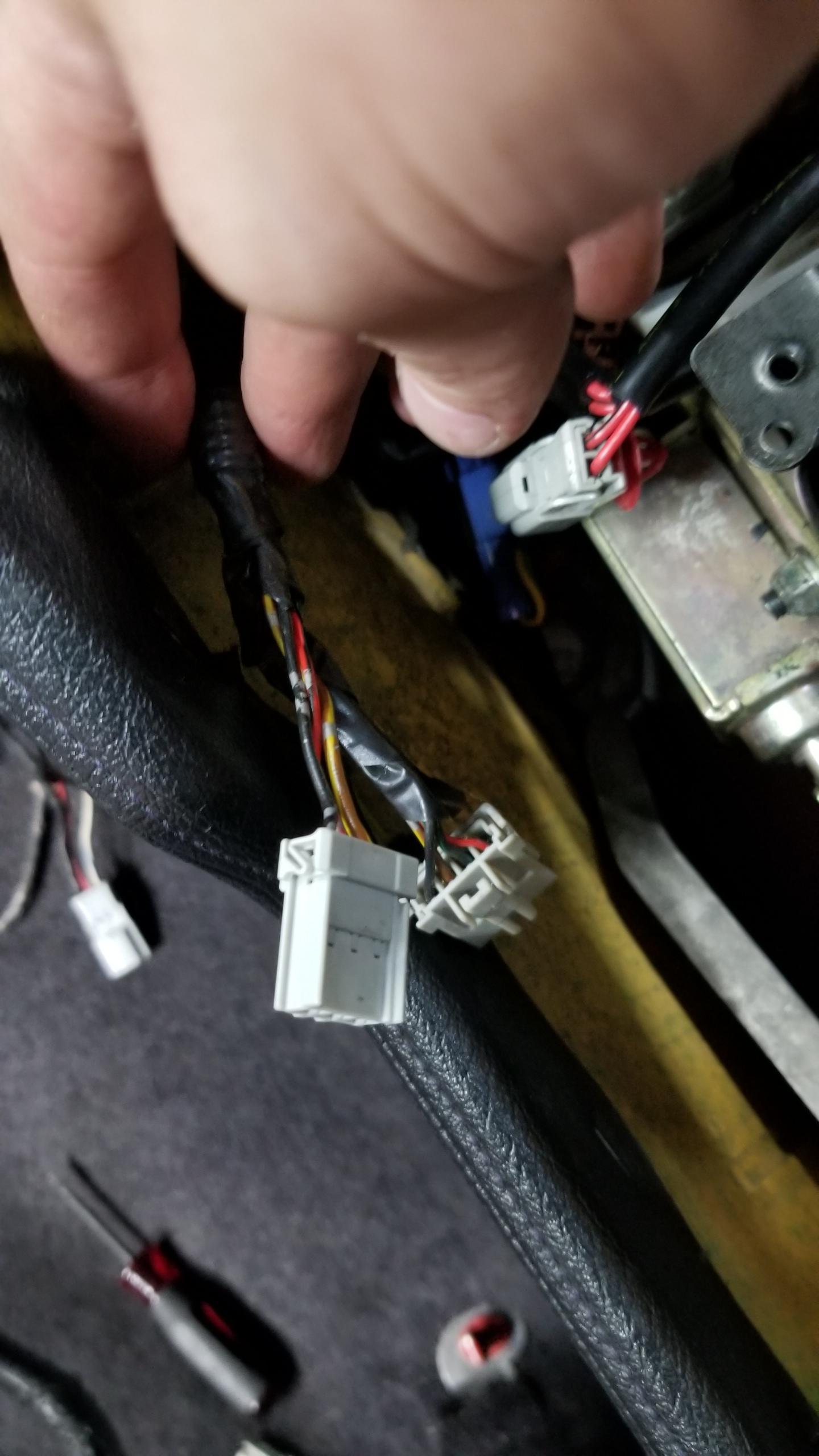
Test install of the patch harness. Zero modifications to the factory wiring, fully reversible, all the new connections are labeled. I'd like to think this is a decent try at a proper wiring job. The original blue connectors still go into their factory spots.
KBUUUGx.jpg


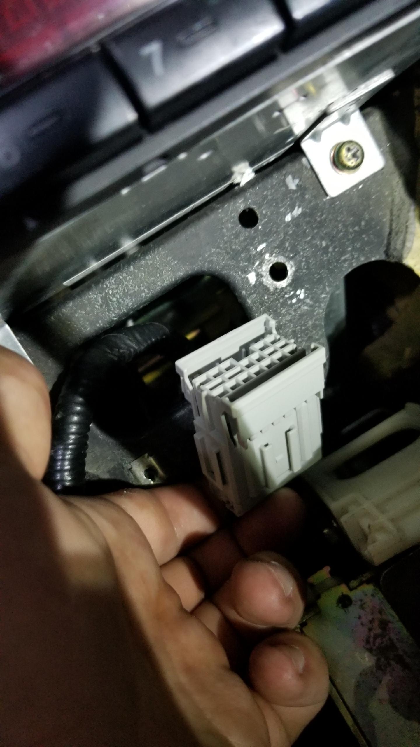
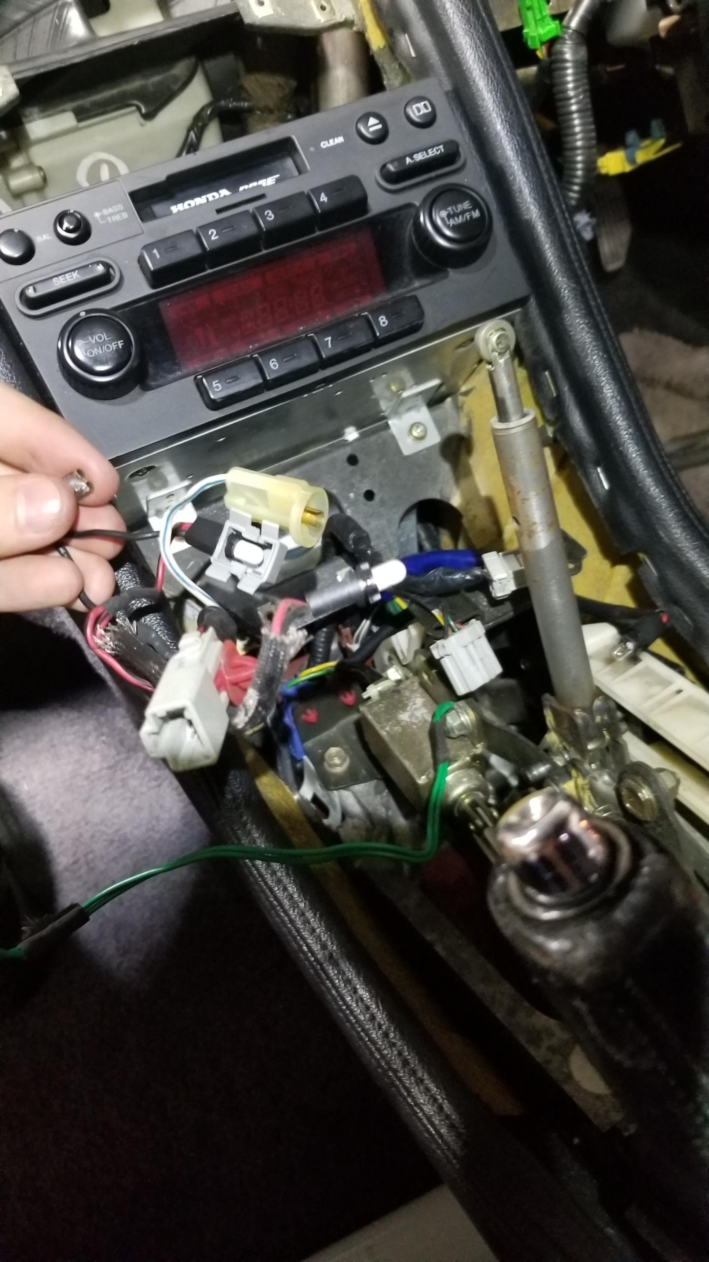
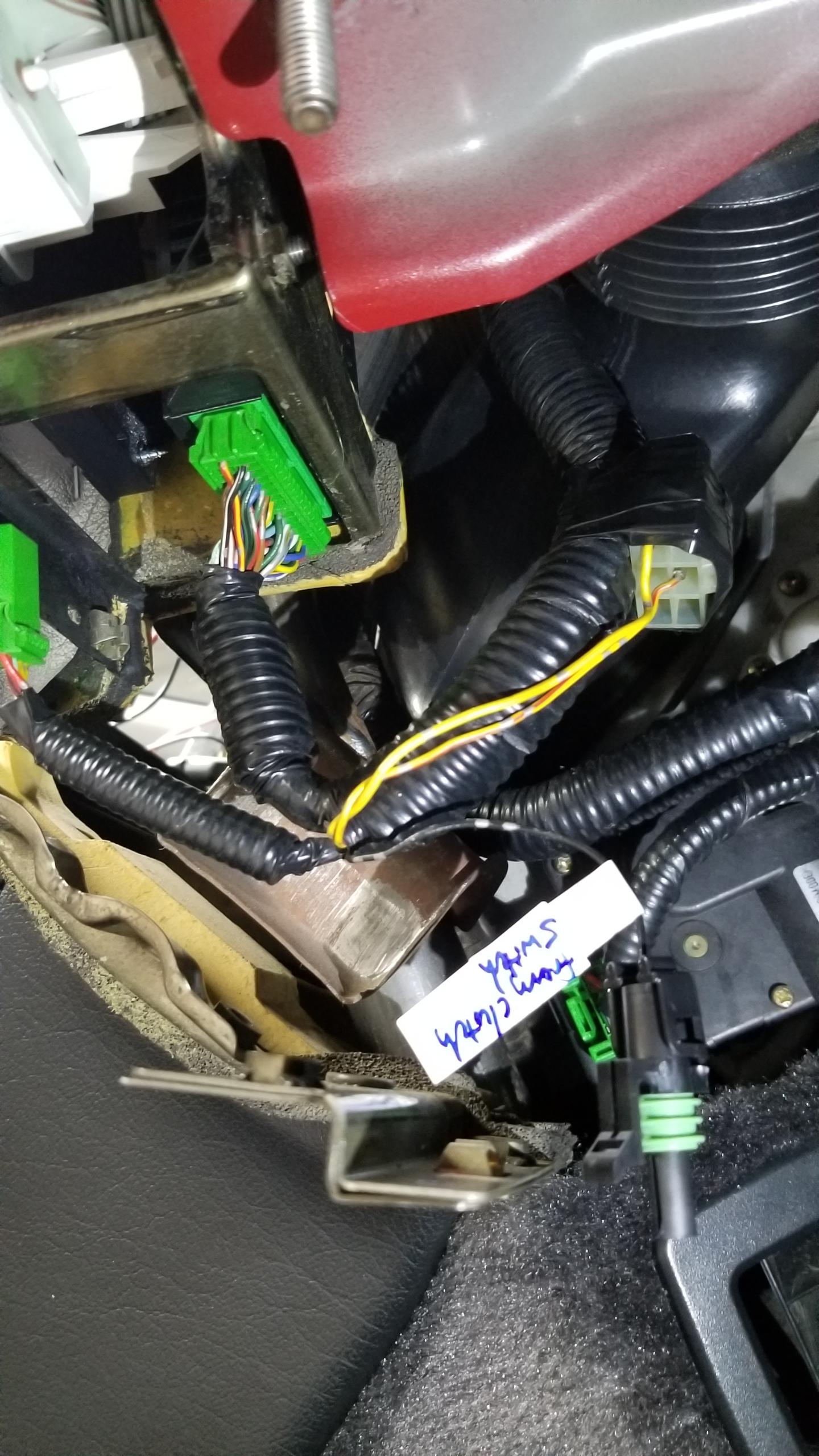
Last thing I got to this day was starting the clutch switch wiring. Step one is finding a ground point for the switch. I didn't see a factory point nearby, but there's this connector just taped to the gauge cluster harness not being used. I'm not sure what it's for, maybe an option feature not being used. It had a black wire which I confirmed was a factory ground wire with a multimeter to various other GND points on the car. I de-pinned the terminal and put a new 1P weatherpack connector on which just needs a short 6" harness to the clutch switch which is just to the right of the pic. So far this is the only real modification to the factory harnesses, but it wasn't being used for anything else anyways.
1LEcSZS.jpg


That's it for today. The wiring is interesting but a little tedious, so it takes longer than I'd think. I'm working on finishing the wiring today, the only remaining work is the 3P clutch switch and the C425 shift console which shouldn't be too bad. Other goals for today is installing the shifter assembly, maybe putting the seats back in, and removing the drive axles if I manage to get that far (might be wishful thinking :rolleyes:). In any case, most of the interior work will be done today.

All this is also based on the SoS clutch kit supposed to arrive on Tuesday. There were more supplier delays, so I had to pay the extra $140 for overnight shipping to get the kit by early this week. As long as there's no other delays (which there shouldn't be...) then I should have it in time for when I need to start putting parts back on the car. I already planned my whole month around taking this week off so I wasn't going to postpone this again.

I'll try to post day-by-day but I tend to work late into the night so there might be a few days in-between updates.
 
Last edited:
Awesome job documenting this. Did not realize the electrical changes were so involved. Are you also going to change your cams and ecu?
 
Awesome job documenting this. Did not realize the electrical changes were so involved. Are you also going to change your cams and ecu?

Appreciate it. All the red wires are just connecting the same pins as before, so visually it looks more complicated than it is. But there's more where that came from :).

No plans to change cams/ecu right now. In an alternate universe where I haven't done my timing belt this year, I might have gotten some used M/T cams and done an even bigger service with the new LMAs and all that too. If I ever have to get that far again I'd take the engine out completely, doing just the TB/WP with the engine in was awful enough lol. Maybe in another year or so after I get the other important stuff done.
 
Back
Top