• Protip: Profile posts are public! Use Conversations to message other members privately. Everyone can see the content of a profile post.

Big McLargeHuge’s 1990 JDM NSX Adventure Thread

Transmission Swap pt2

Give it up for Daayyyy 2.

Finished the clutch pedal switch harness. I learned my lesson this time and used a 2P weatherpack instead of 2x 1P connectors. Black is to a factory ground, blue is to the cruise control unit wire on C425, white is supposed to be the clutch signal to the ECU but the reality is a bit more complicated and I haven't figured out the proper connection just yet.
VnEJaWM.jpg


To get more access to C425 (shift console switch, 12P connector) I went ahead and took out the A/T shifter assembly. 4 or 5 bolts and it lifts out. Take bolts off first then you can get access to take the cotter pin out from the bottom of the shifter.
VNuL4yI.jpg


Here's what it looks like with just the A/T shifter base still in.
R5zPkgY.jpg


Base removed. Plenty of room for activities.
DRQMwTO.jpg


A/T neutral safety switch jumper. I ended up just cutting off the connector on the old shifter and soldered the wires together. They're quite thick, like 10ga or something. Heat shrunk the end and now there's a permanent jumper to allow the engine to start.
9uRMm5e.jpg


C425 harness finished, much more simple since most of the old wires are no longer used. I could've made a disconnect for the clutch switch to cruise control input but the harness is short enough already. The blue wire goes into the factory BLU/ORG wire to the cruise control cancel input. I'll know if I have the wrong NO/NC switch if I can only activate cruise control with the clutch pedal depressed, lol.

The black jumper ties the GND pin to the Drive signal to always send Drive to the ECU(s). The FancyCraft blog here (https://fancy-craft.firebaseapp.com/NSX/report/at-mt/report4.htm) is confusing on this point since it shows a switch between Park and Drive since apparently "idling rises and it is not stable" according to Google Translate. I assume the idle map is different in Park vs. Drive but since 95% of the time when you're idling, you're in traffic and in Drive. We'll see, my money is that it'll be fine.
L2xrHdW.jpg


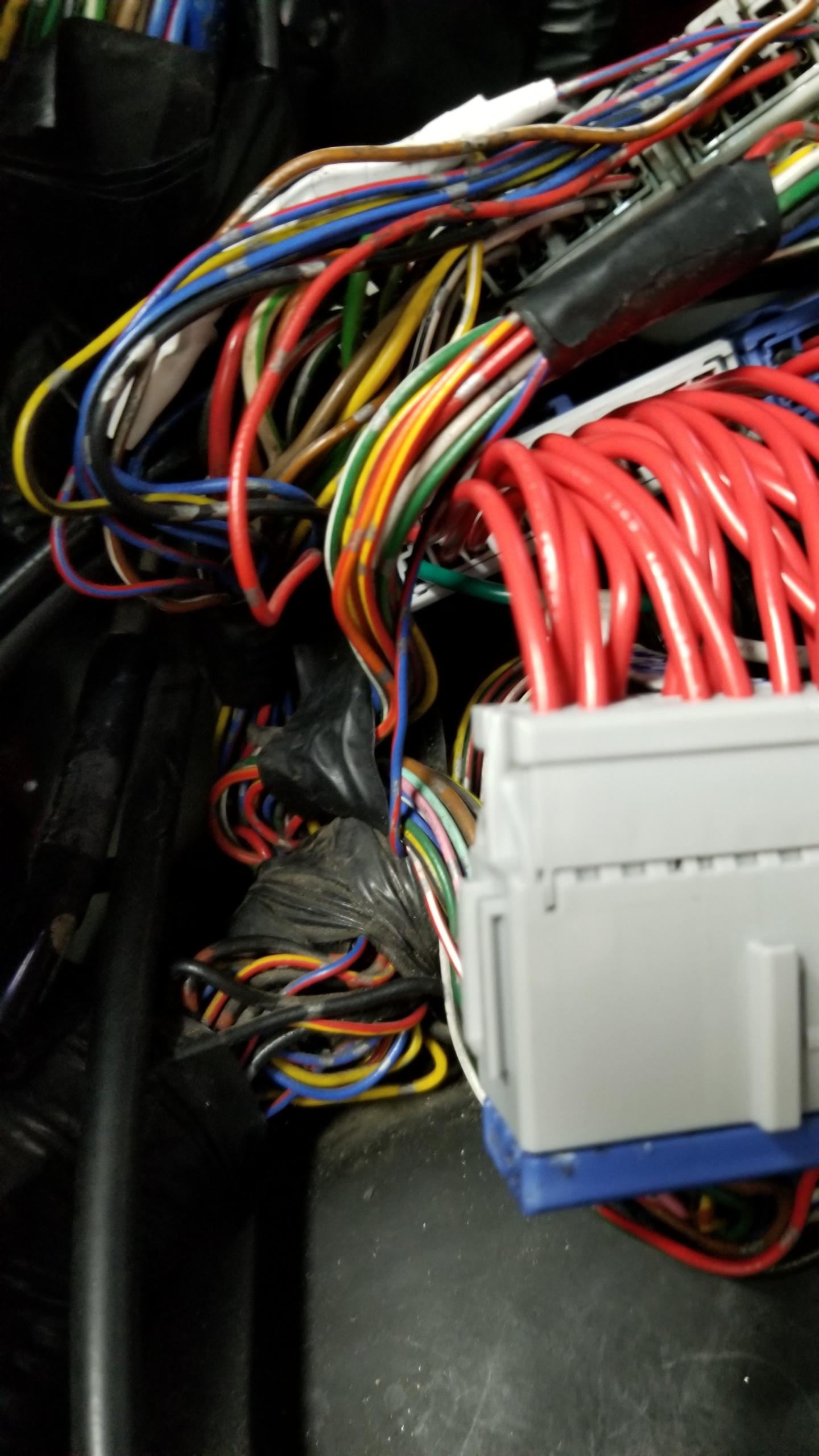
Here's the final patch harness for C161 next to the ECU. It's mostly red wires to the same old wires since there's only two pins I need to mess with.
CFa29Rl.jpg


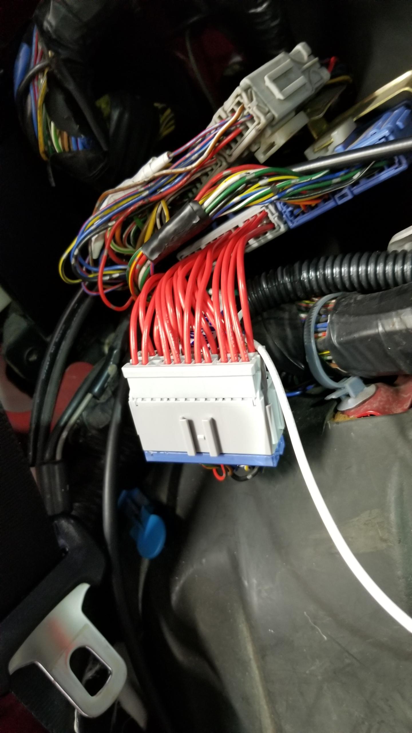
One new green wire to lead into the ECU neutral switch input from my C499 patch harness. There's one other missing pin not included with the factory A/T harnesses, which is a PNK wire for the ECU clutch switch signal input.
7h2gtLc.jpg


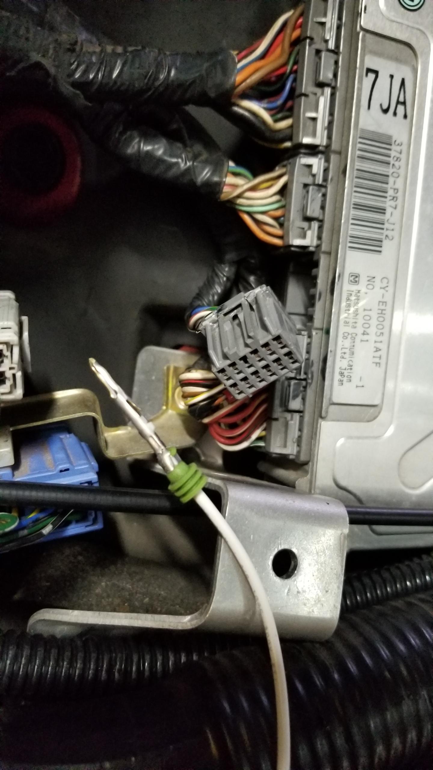
Here's the end of my clutch switch wire to the ECU. There's no female pin on the ECU connector (top row, 3rd from left), so I'd need to find a terminal to add the pin myself. They look smaller than the HD-090 connector terminals I've been using so I need to do more research to find the right kind. Even the FancyCraft author doesn't really know what this input is for, presumably it's to tell the ECU not to use VTEC in neutral/with the clutch disengaged. The car should run regardless.
sE11bgL.jpg


Some final installed harness pictures. Here's C161 again. That was a lot of crimping...
8qPdq46.jpg


Here's C499 from before. Bit bulky with the new wires but the bulkhead panels should fit fine.
0QC8wHd.jpg


C425 harness installed. Connected the YLW wire from here to the backup lights on C499.
UthZXGL.jpg


And finally, the clutch switch connectors. I did some adjustment of the switch with a multimeter to verify where the signal changed based on pedal position. That about does it for the wiring.
cvE7CjW.jpg


For a little underbody work, to fully remove the A/T shift cable I removed the cable cover and pin holding the other end of the cable on the transmission.
Qa1yF9S.jpg


Hanger and rubber gasket for the A/T cables. Remove both and the cable pulls out from the back with the other two underbody brackets removed.
BGNhbGE.jpg


Cable removed.
c0Nn49N.jpg


Time to put stuff on. The new shifter base is a modification by Wayne of the stock A/T bracket. With some new tapped holes and the two top spacers, the bracket can be re-used for the manual shifter bracket.
z9H7juv.jpg


Even OEM brackets sometimes don't fit perfectly. I needed to drill out the 4 bolt holes one size larger to line up right with the factory mount locations. Only a difference of 1-2mm in the end.
NLBEIIr.jpg


New base installed.
jEoPwOv.jpg


Assembling the shifter parts onto the Type-R shift stalk. No instructions for this so it took a little while to put the puzzle pieces together. The exploded parts diagrams for the shifter are clear enough to figure out how to put this all together. New Honda urea grease on all moving parts.
c49X13H.jpg


New shifter bushing snapped into place on the ball stud. There's this microscopic little cushion ball that goes in a hole on the bushing, and is only held in when you slide the shifter piece into the bracket holder. I used some grease to hold the ball in the bushing. So small you can barely see it installed here.
yhfajFV.jpg


Shifter bracket assembled and ready to drop in. The blue block is the Cedar Ridge short shifter mod.
wFeYrI6.jpg


Shift cable connected to the Cedar Ridge short shifter and stalk.
SBMrpVu.jpg


Bracket fully installed with the parking brake back in.
rl5KV0r.jpg


View from the bottom with the shift & select cables installed. Not really any instructions for putting all this in but easy enough to figure out as you go. Now I can sit on the floorboard and pretend I'm a race car driver.

I used pretty much all new bolts & self lock nuts, bushings, grease, etc. Seems to shift just fine, there will probably be more adjusting to do once I connect the other ends of the cables.
3fUMWUq.jpg


That's most of the interior work done, mainly just some adjustments to make and reinstalling the steering column & seats. I'm gonna leave that for later in case I need to get to something inside.

Today my goal is getting the automatic transmission dropped out. We'll see, I've not messed with most of those bolts yet so it'll be a learning experience. As long as I don't separate the ball joints then it should go fine. I also have the big boy axle puller which I'm sure will need to be used. More updates to come.
 
Changing the ECU to manual mode is as simple as removing a single resistor, R4, from the PCB. All 91-94 ECUs are capable of being converted between auto and manual mode this way. There isn’t much of a reason not to do it if you’re manual swapping since it doesn’t cost anything.

I've read that before, but was under the impression that the ECU should be left alone if I don't change the cams. Would doing that change the redline to 8000 RPM and all that? I really don't know enough to say whether or not I should clip the resistor so I'm open to suggestions.

I also see that the A/T control unit was removed in the Speedhunters trans conversion so I might be able to do that. I wasn't planning on removing it but if it's not being used for anything now I might as well.

EDIT: Looking at the A/T control diagrams, the only things I would be concerned about with removing it would be the EPS & TCS control unit inputs since they're tied to the A/T control unit. Blake @ Speedhunters says they got his EPS working with the 4.23 final drive though and they removed the A/T control unit, so it might not matter. I might have to do some testing.

EDIT 2: Never mind, the inputs to the EPS/TCS look to be tee-d in to the connections between the A/T unit and the PGM-FI ECU so removing the A/T unit shouldn't matter. I'm surprised I didn't think about removing the unit until now. Still on the fence about the ECU mod though.
 
Last edited:
IMO the best way to do it, if you plan on keeping the auto cams, is to copy the automatic fuel and ignition tables into the manual ECU code. The R4 resistor switches which half of the ROM the ECU has access to, the lower address space is the manual code and the upper address space is the automatic code.

It would be fairly trivial to copy the fuel and ignition tables from the automatic half of the code into the manual side, giving you a manual ECU tuned to run with the auto cams. If you have questions about this process feel free to PM me.
 
If you have not installed the hard clutch pipe B, the long one located inside the passenger compartment: I recommend pulling the dash at this point.

There isn't much left holding it on and installing this pipe is a major pain. The pedals are easy compared to getting the hard pipe in with the dash in place. Rather easy without the dash.

Does the FancyCraft wiring reuse the AT transmission connectors? If so, remember to make a couple of null connectors to keep the unused ones unspoilt.

**

As for my AT->MT Guide, distribute away. It started off as an outline from WhrdNSX, I made it a bit better and you are making it great. It really needs to be on the NSX Wiki, but I cannot figure out how to make it work.

My wiring is a bit vague as I lost my notes, but is real close.

I have two issues remaining:
1. Verify the neutral ECU input
2. Investigate the cruise control non-op.


**

MotorMouth93 What are the diffeneces are between the MT and At ECU's other than the ignition and fuel tables?
 
Last edited:
IMO the best way to do it, if you plan on keeping the auto cams, is to copy the automatic fuel and ignition tables into the manual ECU code. The R4 resistor switches which half of the ROM the ECU has access to, the lower address space is the manual code and the upper address space is the automatic code.

It would be fairly trivial to copy the fuel and ignition tables from the automatic half of the code into the manual side, giving you a manual ECU tuned to run with the auto cams. If you have questions about this process feel free to PM me.

Thanks John. I'll PM you in a bit when I get the chance, I'll need a lot of help :wink:

If you have not installed the hard clutch pipe B, the long one located inside the passenger compartment: I recommend pulling the dash at this point.

There isn't much left holding it on and installing this pipe is a major pain. The pedals are easy compared to getting the hard pipe in...

Does the FancyCraft wiring reuse the AT transmission connectors? If so, remember to make a couple of null connectors to keep the unused ones unspoilt.

**

As for my AT->MT Guide, distribute away. It started off as an outline from WhrdNSX, I made it a bit better and you are making it great. It really needs to be on the NSX Wiki, but I cannot figure out how to make it work.

My wiring is a bit vague as I lost my notes, but is real close.

I have two issues remaining:
1. Verify the neutral ECU input
2. Investigate the cruise control non-op.

I got the aftermarket stainless braided clutch line from Wayne so won't be bothering with the hard lines. Planning on running it straight from the master underneath with the coolant lines.

Their wiring uses the A/T linear solenoid valve and lockup solenoid valve 3P/2P connectors for the M/T neutral switch and backup lights. There will be a few unused connectors so I should look at covering them as you say.

Once I finish all this I'll make a final revision of the swap guide and post it with my learnings.

On your #1 , with the FancyCraft wiring diagram you remove the neutral signal from the shift position indicator and re-route it to the M/T neutral switch, with the other side being ground. Should just be a simple replacement of the A/T neutral signal.

For #2 , it might be that the cruise control is looking for the opposite signal from the clutch switch than you're providing. If you can activate cruise with the clutch pedal in/disengaged but not out/engaged then that would be the issue. FancyCraft says the signal to the cruise should be normally closed, so with the pedal up, the 3P switch I have will be grounded on all pins (normally closed). It's the opposite for the signal to the ECU so I don't know what the right answer is just yet.
 
MotorMouth93 What are the diffeneces are between the MT and At ECU's other than the ignition and fuel tables?

There aren't really any major differences that would seriously affect drivability it's just a huge number of minor changes to the way the ECU handles things. Oh and it enables the clutch switch input I believe.
 
Last edited:
Transmission Swap pt3

This is where the fun begins.

Goal for Monday was dropping the auto transmission out. I got most of the way there.

Draining A/T fluid. Looked a decently new shade of red.
ZI2dJP3.jpg


Removed the air filter box and three connectors/two bolts for the control box and set it aside. The FSM says not to remove the vacuum lines so I didn't touch them.
M9Qt8XG.jpg


One of the pics of my marks on the camber adjustment bolts for when I drop the control arms.
mmBeY9V.jpg


Right side control arm and toe link dropped. I removed the sway bar too since I have new poly bushings & brackets to put on. Left the lower ball joint alone so I don't break the expensive arm.

This was the first time I messed with most of these bolts so it took a little longer than average to figure them out. This side was a bit crustier than the left side, but big plus is that none of the bolts were seized inside the bushing collars so that saved a lot of time. Overall fairly easy to remove and punch out of the bushings.
7xIbY8c.jpg


Little bit out of order, but before removing all the arms I had to tackle the axle nuts. I knew they were going to be tough. Un-staked the lock tab and soaked with some Kroil and tried my electric impact & 36mm socket, nothing. Then tried the jack handle + 1/2" breaker bar I used on my crank pulley bolt for about 5ft of leverage, still nothing and I was real close to breaking my breaker.

Finally had a use case for the ATF/acetone mixture which I then applied to the the nut and let sit for a little while.
18MDSxl.jpg


The ATF/acetone mix plus an even larger 1/2" electric impact actually did the job. I didn't think the impact would work but I sat there for about 10 seconds just railing on the nut and then it began succumbing to its fate.
aivwKcA.jpg


Overall progress pic. Nuts off and ready to pull the driveshafts.
jchU2sC.jpg


From reading multiple Kaz blog entries about the shafts, I anticipated mine would be seriously stuck in place. I preemptively bought an OTC 6574 hub puller rated for 20 tons. Was it overkill? Oh yeeeahhhhhh. But felt so good setting the thing up and just sending it.
z9GdwcP.jpg


Another hour or two and the shafts were out. That might seem like a long time after the shafts were already pressed from the hubs and you'd be right. The right shaft was easy, just popped it out from the intermediate shaft with two pry bars 180 degrees apart, then press the hub side out and out it comes.

The left shaft was much harder, there's just no room to get one end of the shaft out with the other installed. I'm sure there's some tribal knowledge here for doing it in 5 minutes but a friend and I tried removing the trans side first with no luck (not enough room to pull it free), tried the hub side, disconnected the strut tower to get more clearance, and kept pressing it and after much struggling got the hub side dangling free, which allowed the trans side to be pried out in short order. Learning experience I suppose...
k7Vy6BD.jpg


There they are, the little assholes. They will be rebuilt before re-installation.
IfhvjgJ.jpg


As you can see, the right side inboard boot split a while ago and slung grease everywhere. I kept driving on it up until this point so hopefully the internals look okay to reuse.
r42EKXG.jpg


Removing the intermediate shaft. You need to punch out the shaft from the trans before you can remove the bracket, which sucks since it's not quite a "light press fit" like the FSM says. Took a lot of hammering on the tabs to get the shaft out enough to this point. The right technique seems to be to punch it at three different points instead of just one or two like shown.
Q0KEiDi.jpg


Even still, the battle was eventually won.
Uc2BZ8e.jpg


Starter removed. If you remove the front beam with the engine mount this might not have to be fully removed before dropping the trans, but at the moment I plan to do it with the front beam installed. The bottom bolt is a real big pain in the ass to get out, an electric ratchet is pretty much required.
WZnu11F.jpg


Hoses removed from the ATF cooler. They were stuck on there really tight and I ripped one of them in half by hand. Long-nose articulating needle pliers and hose pliers are almost required.

This is how much coolant poured out from the two hoses. I actually accidentally removed another hose just in front of the cooler which is where most of this came from until I realized my mistake. Either way I have new coolant to add.
WK5swqx.jpg


In progress with removing the A/T drive plate bolts. There's another walkthrough on Prime of this part saying it's a very scary procedure but I didn't find it that bad. Pretty much just use a 6-pt socket, hold the crankshaft pulley in place with a socket or pulley holder/what have you with your right hand, and break the bolt loose with your left hand. It's a soft metal but only has maybe 10-15 lbft on it so easy to break loose. Rotate the crank clockwise until the next bolt is at the top left position, repeat until all 8 bolts are out.
Rv4lTss.jpg


Here's the point that I got to last night before calling it in. All that's holding the trans in now is the mounting bolts to the block and the three mounts. Today I'll drop it down, replace the rear main seal, maybe fit the clutch tank & line, etc. I expect the clutch kit to arrive by tomorrow. If it's delayed again I'm pretty screwed.
7meiTIe.jpg


More updates to come. About at what I would consider the halfway point, many of the difficult hurdles have been overcome so far. If I had to guess, the most difficult part of the whole thing might be fitting the manual trans back onto the engine. Lots of things need to be perfectly aligned..
 
There aren't really any major differences that would seriously affect drivability it's just a huge number of minor changes to the way the ECU handles things. Oh and it enables the clutch switch input I believe.

Sounds like something I would be interested in but I have no experience messing with ECUs.

Do we know what the clutch switch input to the ECU actually does? FancyCraft says it might disable VTEC with the clutch disengaged but I'm not sure.

I still don't know how to connect my wire to the ECU female connector so it's just hanging there at the moment.
 
Transmission Swap pt4

No clever title, SSDD.

Preparing to drop the auto transmission. The hydraulic table has two large rubber block to support the engine since with the trans out, it's only supported by the right mount and one bolt on the front mount. Hopefully the load is low and spread out enough so I don't dent my new expensive pan...
XkGxKOa.jpg


The two front engine mount bolts can be removed with the front beam still installed. One other large 17mm transmission housing bolt to remove right next to the mount.
UiPXf7q.jpg


Rear mount removed. Two more large bellhousing bolts further back, plus two on top that can be taken off with a long extension and breaker bar from above.
bdfbtN3.jpg


With all the large bolts and mounts removed (plus the drive bolts, connectors, ATF cooler hoses, ground cable, starter, etc.), the transmission can be pulled back from the engine. Once it clears the dowels it can pretty much be lowered right away.
m4X6E2Y.jpg


Halfway lowered down, just checking that there's nothing stuck on. With the transmission scissor jack it's surprisingly easy to bring it down.
oR3iblG.jpg


Finally exposed the drive plate.
0NmnnSx.jpg


Now go sit in time-out and think about what you've done.
3SGxrdK.jpg


Finally was able to migrate over the EPS speed sensor to the M/T diff speed sensor spot. There's a small washer under the sensor bolt to pull it away from the ring gear teeth. There's already a spot for the connector to clip to on the bracket.
lKpuwER.jpg


That will go up in there at some point.
0oiUR3H.jpg


Rear mount has seen better days. My new one looks much better.
DqcK3LU.jpg


A/T drive plate removed after impacting off the 12pt "flywheel" bolts. They have very thin heads so you really need to be square on the bolt and take more care than usual with the impact.

It looks like the RMS was probably leaking a bit. Good thing I'm replacing it.
eVpkUus.jpg


Seal holder removed. This is the factory method for replacement of the seal, doing it with the holder still on the engine would be difficult to do correctly.
x0XZrjA.jpg


The seal is really stuck in there, so I drilled a small hole into the seal and put a screw inside to pull the seal out.
cS0oMMC.jpg


That was a lot of yanking.
wFqR0vg.jpg


Seal holder cleaned up.
4bqT8p1.jpg


New rear main seal installed. That took a lot of hammering with the seal driver to get the factory specified clearance between the holder and seal, verified with feeler gauges. Again, would be very difficult while still in the car.
yvSxmw6.jpg


Back to the car, the A/T cooler bypass hoses I was planning on using were just slightly too small to fit on the pipe nipple. Since I had bought a stock hose for testing purposes, I tried fitting it like Drew's guide suggested and was able to make it work comfortably enough. Not quite as elegant as I wanted but I don't really have the time at the moment to hunt for a new straight run of hose to fit. I'm fine eating my own words for once.
rmsTOG2.jpg


Parts laid out for the seal holder install. New bolts needed with factory thread locker applied like the water pump bolts.
shO3BAA.jpg


Aaaand it's in. Was a little puzzling to fit on the dowels but managed to make it work before the Hondabond cured. Oh yeah, and I spend an hour or two cleaning off the side of the engine too. Not bad for 30 (31?) years old.
2Jj6kGG.jpg


Back to the front, I decided to put in the clutch fluid tank and braided line. The line came with fitting for the master cylinder and the damper on either end. I bought some rubber bracket clips to mount the line along its long journey to the rear. I also put in a shiny new ground cable since my old one was over-tightened and wouldn't hold the battery terminal right.
wDrhV2y.jpg


Rest of the clutch line ran along the center tunnel. I considered using the bolt locations further inside the tunnel away from the ground but the bolts would be very hard to get to. This will be covered by the lower tunnel cover anyways. I might end up moving them depending on how well it goes together in the end.
q1bfUYG.jpg


Quite a lot of length left to make it to the transmission. I might have to find a place to tie up the extra line but I'll leave the final mounting locations until the end.
Dl1BSpN.jpg


Connectors labeled to make install easier when figuring out where to connect the new sensors. Only about half of the connectors will be re-used.
MK8wCA8.jpg


Here's a nice final picture of where I left off. Ready for the installation of the flywheel & clutch.
Y0XbkDo.jpg


Tomorrow (today) I will be rebuilding the driveshafts/int shaft and do a bit more interior work with the pedals & wiring which should keep me busy for the time being.

Unfortunately, I will soon hit a wall without the Science of Speed clutch kit & damper delete to install. I tried emailing and calling them today to figure out what the deal is but got no response. I'm quite disappointed that I paid for overnight shipping to get the kit by today or tomorrow, if I don't get it by Wed/Thurs I'll be in real trouble since I only have this week off and can't move my car from the communal lift without drive axles. All I can do is hope they ship it out tomorrow, but I'm getting tired of the delays and false delivery dates.
EDIT: Called again this morning and they said it should arrive Thursday. At least I should be able to install it the same day.
 
Last edited:
re: rear main seal replacement can easily be done with the "drill hole + screw" works with the RMS carrier in place. While the seal is slightly harder to install with the crank shaft in place, it is quite managable.

re: flexible clutch hose. Your method of install appears to be in the way of reinstalling the plastic tunnel covers...? How will you reinstall them

For those of you that don't have multiple jacks, I use a custom cut 1x2" length of wood between a block support (where the piston numbers are engraved) and the garage floor. This minimizes the footprint and allows the transmission jack to have extra room. The wood also insures the jack won't sag down overnight and put pressure on the coolant hoses.

I did your method of RMS removal with the holder off since a guy on the FB group said that's the best way to do it and prevent future leaks. It let me clean the holder more thoroughly at least. The problem is that you can't check the clearance on the back of the seal with the holder in place, when I replaced it it was ~0.4-0.5mm around but one side of the seal was >0.8mm and took a lot more hammering to get in spec so it might've leaked if I had done it on the engine.

I haven't tried putting the tunnel cover back on, I figured they would go around the clutch line but you're probably right. There's more factory brackets inside the tunnel holding the A/C lines so I'll probably put it up there, just a pain to get to.

Agree on the wood block(s), the lift table I'm using is bulky. There's enough room for my trans jack but not much else.

Almost forgot. The last leak I have on the engine is from these little plugs. I'm not sure what they're for, but is this something I can remove with an allen key and add some Hondabond or something as a thread sealant to reinstall them?
rh3hQ06.jpg
 
Those plugs are tapered plugs used to block off oil galley drill holes. You can back them out, clean the threads, apply a couple layers of thread tape, and put them back in. Hondabond would work too but you need the surfaces completely free of oil for that to work which could be difficult due to the angle of the heads and having oil drip down slowly.

I agree with drews method of replacing the oil seal. I only remove the carrier plate if I'm also removing the oil pan, otherwise you risk a leaky oil pan after reinstalling the carrier which really sucks if you have aftermarket headers. If the seal is crooked by a fraction of a millimeter thats not going to affect anything. Checking the clearance behind the seal isn't really necessary, lots of engines don't even have a stopper behind the seal and you can knock the seal all the way back into the crankcase if you aren't careful, its pretty standard practice on higher mileage engines to leave the seal poking out a millimeter or so so the lips aren't riding on the groove in the crankshaft created by the original seal and that doesn't cause any issues.
 
Last edited:
Give it up for Daayyyy 2.

A/T neutral safety switch jumper. I ended up just cutting off the connector on the old shifter and soldered the wires together. They're quite thick, like 10ga or something. Heat shrunk the end and now there's a permanent jumper to allow the engine to start.

The black jumper ties the GND pin to the Drive signal to always send Drive to the ECU(s). The FancyCraft blog here (https://fancy-craft.firebaseapp.com/NSX/report/at-mt/report4.htm) is confusing on this point since it shows a switch between Park and Drive since apparently "idling rises and it is not stable" according to Google Translate. I assume the idle map is different in Park vs. Drive but since 95% of the time when you're idling, you're in traffic and in Drive. We'll see, my money is that it'll be fine.

I'm fairly sure the A/T neutral switch is only required if you are going to use the A/T ECU setting. On the M/T, the ECU gets the neutral signal from the M/T neutral switch on the transmission.

Similarly, the Park/Drive switch is for the A/T ECU to adjust idling to account for the extra load on the engine in Drive. There are some "ATingear" fuel settings for this purpose that are not used on the M/T setting. The clutch switch performs this function on the M/T cars.

Thus, if you switch your car to M/T mode (assuming you run the AT fueling on the MT maps), you should not need either of these connections. Did you remove the key interlock switch on the ignition column? The Fancycraft dude did it and I think it's clever.
 
Those plugs are tapered plugs used to block off oil galley drill holes. You can back them out, clean the threads, apply a couple layers of thread tape, and put them back in. Hondabond would work too but you need the surfaces completely free of oil for that to work which could be difficult due to the angle of the heads and having oil drip down slowly.

I agree with drews method of replacing the oil seal. I only remove the carrier plate if I'm also removing the oil pan, otherwise you risk a leaky oil pan after reinstalling the carrier which really sucks if you have aftermarket headers. If the seal is crooked by a fraction of a millimeter thats not going to affect anything. Checking the clearance behind the seal isn't really necessary, lots of engines don't even have a stopper behind the seal and you can knock the seal all the way back into the crankcase if you aren't careful, its pretty standard practice on higher mileage engines to leave the seal poking out a millimeter or so so the lips aren't riding on the groove in the crankshaft created by the original seal and that doesn't cause any issues.

Got it, I've gotten some thread tape to reseal them.

Ok I give, lol. Agree it risks oil pan gasket leaks. I covered the exposed gasket when I was cleaning, cleaned off old material, and re-applied Permatex Permashield to both sides before putting the seal holder back on. The Permashield that Old Guy suggested seems to be working great so far, the rest of my pan is still completely dry. If this messes it up I will be very sad.


I'm fairly sure the A/T neutral switch is only required if you are going to use the A/T ECU setting. On the M/T, the ECU gets the neutral signal from the M/T neutral switch on the transmission.

Similarly, the Park/Drive switch is for the A/T ECU to adjust idling to account for the extra load on the engine in Drive. There are some "ATingear" fuel settings for this purpose that are not used on the M/T setting. The clutch switch performs this function on the M/T cars.

Thus, if you switch your car to M/T mode (assuming you run the AT fueling on the MT maps), you should not need either of these connections. Did you remove the key interlock switch on the ignition column? The Fancycraft dude did it and I think it's clever.

I think this finally makes sense to me now :rolleyes:. After this week when I verify I have a driveable car, I'll look into the steps for changing the ECU to M/T mode and copy over the A/T fuel/ign/whatever tables. The A/T neutral safety bypass will let me start the car until I get that figured out. The FancyCraft wiring philosophy re-uses the A/T ECU mode so everything I've been wiring has followed that method.

I assume at that point then the ECU will actually use the clutch switch input wire which is currently just dangling nearby. I messaged Joe @ Cycle Terminal and ordered new female terminals that should fit the ECU connectors. It will be interesting to see if my cruise control still works with the clutch switch I have. Not that I ever use it anyways.

I haven't removed the key interlock or the A/T control unit yet. Thinking about routing the parking brake switch to the key lock like Drew suggested so that it forces you to put the brake on before shutting the car off, but there might be some use cases where that's not desired like if you cook your brakes and want to let them cool off without the parking brake engaged.
 
Transmission Swap pt5

Today is driveshaft day. I had more planned but this took waaaay longer than I thought it would. I didn't get as many pictures as usual since I was both very frustrated and my hands were always covered in grease.

Starting with the left axle. The boots were still good so there was still plenty of mocha ice cream left inside.
2yVqsNp.jpg


My little setup.
GFp9Fet.jpg


One shaft mostly disassembled. I used different color paint markers to keep the orientations and all that the same, but during re-install it didn't quite work out as well as I hoped. Just inexperience really..

Snap ring pliers are required. Even then it's super annoying taking all the snap rings off, little less bad putting them back on.
4CtnN8x.jpg


Overall, really no noticeable wear to speak of on the moving parts. That's good.
o5ANF2Z.jpg


Of course I had to go the whole way. 12 roller bearings x a million needles per bearing = very long and tedious process of reassembly with new banana grease. Put some music on and let your brain take you away. Just don't lose a pin.
HlLXfHq.jpg


One down. Couple more hours to go.
Or8w306.jpg


Since my cups and shafts were super gross looking before I sanded and painted them. I say sanded, but some of the cups were so rusty I had to chip off the rust with a chisel. I used Rustoleum high heat paint which is matte and probably not ideal for this application but it's what I had on hand. Seems durable enough so far.
g0K2phc.jpg


Finally, after about 5 more hours of trying to put everything back together again (seriously), one shaft is almost reassembled. I stole Kaz's method of the red straw to balance the air in the boot during shaft length adjustment.

Oh yeah, and it was my first time using the CV boot tool so I managed to break the first clamp I used by folding the tool over too far which broke the tab on the strap. I wish there were extras in the Honda kit, I had to order new ones today or might try and aftermarket one if I can get it faster.
OkC39yu.jpg


There's almost two hours between the last pic and this one, that's how bad I am at putting these things back together, lol. I'm a lot better with the banding tool but still have to get an extra band for the one I broke.

Anyways, this whole process took me literally all day and definitely makes the Top 3 List of most frustrating NSX jobs I've done so far. At least the shafts look a lot better, no play between the rollers and cups, and no split boots.
ntaoqad.jpg


Oh yeah, and this just arrived an hour ago. Later than promised but it's here now and that's all I care about. They threw in a really nice polo shirt too for the trouble which is appreciated.
xclncxC.jpg


Also just ordered some misc. stuff I was missing. I needed another adapter for the clutch line to the slave cyl since the braided line will be attached directly to the slave cyl. I will need to sell the SoS damper delete I just got, I didn't realize it wasn't even needed :rolleyes:. Let me know if you want a discount on one.
 
Last edited:
Today is driveshaft day. I had more planned but this took waaaay longer than I thought it would.
Finally, after about 5 more hours of trying to put everything back together again (seriously), one shaft is almost reassembled.

Were you reassembling it by yourself? [MENTION=18194]Honcho[/MENTION] and I struggled a little bit to put one back together, snap rings were a pain and boot bands aren't the most fun. We did say to each other that it would be a nightmare to do alone, and I guess you just confirmed that if you didn't have help. One thing we did was put the shaft in a vice to help keep things steady.
 
Were you reassembling it by yourself? @Honcho and I struggled a little bit to put one back together, snap rings were a pain and boot bands aren't the most fun. We did say to each other that it would be a nightmare to do alone, and I guess you just confirmed that if you didn't have help. One thing we did was put the shaft in a vice to help keep things steady.

Yes, by my lonesome. My usual helper friend wasn't available. I had a vice but it still sucked, especially putting the end cups back on the rollers. Two people would be the way to go.
 
Transmission Swap pt6

Big day today.

Starting with the little stuff. Both front head plugs resealed with thread tape. Should've had a rag under it for the bit of oil that spilled out.
KJCK7o6.jpg


Clutch kit carefully disassembled to put in the car. The SoS 275 is a single friction disc design which I actually didn't know about, I honestly thought it was the OEM dual friction disc/midplate design. Thankfully it wasn't lol, the factory discs look a lot more complicated to install...
DZ2yTkD.jpg


Everything was ready for the flywheel to go in, so instead of the OEM flywheel holder tool or wrench/screwdriver trick, I used a breaker bar on the crank side and wedged it against the lift ramps so the engine wouldn't turn the wrong way. Worked just fine.
iEgWdcn.jpg


Flywheel installed with new bolts & threadlocker in multiple stages. Pretty easy so far.
VcvzMJ0.jpg


And the friction disc/pressure plate/bearing installed with the included clutch alignment tool in multiple stages until final torquing. The release bearing is sitting in the pressure plate teeth like it should be, I've read enough threads on Prime of people having to pull the gearbox off again since the bearing wasn't installed right and I don't want that to be me.

That's the whole clutch kit installed, it was actually way easier than I expected. Good on SoS, for once I can install an aftermarket part and it installs perfectly. No midplate initialization or messing with all the OEM parts to get it set up, just align the orange marks (hidden in pic below) and carefully torque everything together. Noice.
3bIwqP9.jpg


5-speed final prep for install into the car. Two new dowel pins to facilitate insertion, light film of Honda urea grease on the bearing collar, very light film of Sachs spline grease on the shaft & clutch splines, and the release fork greased and inserted into the spring-loaded hanger. Just like the bearing & pressure plate, there's plenty of instances of people forgetting to put the release fork in before fitting the trans to the engine. This is definitely something I only want to do once.
JEgUj0b.jpg


Here's a nice little final picture of the engine before the trans went in. It would be nice to do the coolant hoses now too but I'm saving that for later.
7YcgrO0.jpg


Can't forget to pack the internal groove of the release bearing with urea grease. Thanks to Goldnsx and Kaz for their thread here (http://www.nsxcb.co.uk/showthread.php?14344-My-gearbox-revision-thread/page5), I've read through their posts a few times for both my gearbox rebuild and this process. Definitely would've missed some important items without their info sharing.
GG3WKPY.jpg


Prepare for takeoff.
8mubHqO.jpg


Docking procedure complete. That was about 1 1/2 hrs of wresling, wriggling, adjusting again and again until the trans seated correctly. I think the major hangup is fitting the input shaft splines into the clutch disc, once it's past that, the end of the shaft just has to align with the pilot bearing inner race and then it's just the dowels to clear. Once it was pretty much flush (just the dowels left) I put in three bellhousing bolts by hand and everything sits flush. That was about as physically painful as I expected it would be, so if you point out something I should've done better I don't think I'll have the willpower to pull the trans back off, haha...
DP3qzbb.jpg


I had the clutch fork inserted all the way into the retainer, and the only thing I'm concerned about is that the fork tines are sitting on the end of the bearing instead of inside the groove since I didn't pull/push the fork in myself when I mated up the transmission. I can't really move the fork by hand now, which I think is like it should be? Here's the fork with the trans all the way on. I might be overthinking it.
VjMQd0n.jpg


Starting to put the major bolts back in so I can remove the jacks. New engine stiffener installed.
IS0U7bq.jpg


Rear mount installed with loose through-bolt to hold the drivetrain up. This required some creative jacking and prying to get the bolt holes to line up properly.
U5fwRtv.jpg


Front mount installed, mostly. Unfortunately, a minor disaster occurred where the lower mount bolt on the transmission side stripped out the aluminum threads on the trans case and the bolt wouldn't snug up. The top two bolts torqued down fine.

The stripped threads are fortunately on the easier to access bolts and it's a through-hole to the other side of the bellhousing, so I think it can be Helicoiled by removing the front beam to get room to drill/tap. Either I'll talk to a shop that can do it for me properly or I might buy my own M10 helicoil kit though this might be something I'd rather leave to a mechanic. The car should be fine to drive for a bit until then, the bolt's got some meat left to grip to, but I need to get it fixed.
SMoluEu.jpg


Left mount installed to the transmission. Now that all the mounts are in place, I tightened the through bolts in sequence (I think front, right, left, rear) to properly set the bushings and whatever so they don't twist and cause vibration.

I also started installing some accessories like:
-starter with new M/T length bolts, cleaned off contacts, reconnected wires
-slave cylinder w/urea grease and new rubber boot
-connected up the neutral & backup light switches, diff speed sensor, and VSS1, bolted down wiring harness clamps, attached ground cable
MChJpTt.jpg


The SoS damper delete, though I'm not using the delete block itself, comes with a 1/8"x -3AN fitting to the slave cyl adapter. Fortunately, Wayne provided a 1/8"x -4AN fitting that will connect directly to the slave cylinder adapter.
eUIVPDr.jpg


New fitting installed onto the adapter plate. The O-ring goes into the slave cyl, I lubed it with some brake fluid and torqued the plate on (no pics). Today I will connect up the hose and do the final routing & bleeding of the system.
4QD92gf.jpg


Progress pic. If nothing else, it's nice having a new shiny part installed with new hardware and all that, much nicer than a 31 year old grimy and bulky automatic. There seems to be more room to work around this case due to the smaller size.
LHfiCp2.jpg


I'm starting later and later every day since that pic was taken at like 3am, my poor sleep schedule..

Today I'm picking up the replacement CV boot to finish the driveshafts up, finish & bleed the clutch system, install & test shift cables, and do some misc other items. Saturday will be reinstalling all the underbody parts & suspension, MTF filling, etc. to prepare the car for start-up and driving. Sunday will most likely be the day where I'll know whether I have a car or a pretty red brick on my hands. I suppose I could try to start the car at the end of today but I'd prefer to take it slower and make sure everything is set up as good as I can make it.
 
Last edited:
Stick a mirror (or camera) up there and try to get a look through the clutch fork hole. IIRC the clutch fork could be wiggled fairly easily by hand once its seated correctly.

You were right, I stuck an endoscope in the hole and the fork was pushed up against the front of the bearing instead of the groove. That was what I was worried about. Just spent some time undoing my work to separate the trans and engine by 1cm or so which released the pressure on the fork and let me reinstall it in the groove. Lesson learned, don't clip the fork in fully before mating the trans. Only an hour or two of wasted time to take the bellhousing bolts and mounts off and back on again.

Wrong.
20200911160411.jpg

Fixed.
20200911173108.jpg
 
Last edited:
So glad you caught that now! When I read your first post up there about it, I was like "oh no it should wiggle! Dont start putting everything back on!" haha. I was hoping you might try to cycle the clutch though before you got too far anyways, but no matter, crisis averted!
 
I would go one step further: install, bleed and test the clutch slave. You can test out the clutch to a certain degree, which is a cheap test at this point.

After seeing the install of the soft clutch soft pipe: I would still recommend doing the hard pipe for anybody doing this. Looks like the only extra work is pulling the fuel tank....which is pretty easy if you have the car high enough to get the transmission out....maybe an hours worth of work. Especially if the fuel filter is going to be changed out too.

One can get by without pulling the dash, but trivial if you do. Pulling the dash allows replacement of the defroster grill (if cracked) and servicing of the evap unit...at a minimum grease and clean. Drives me up the wall when my vent doors make noise on start up!

Also a lot easier to deal with the shifter wires... And while I'm on shifter wires: Honda uses the same switch+connector on the Civic's and Accord of that era.

I'm keeping all my AT parts in case of a crashed vehicle and I can swap out critical parts before insurance takes it away (always make sure the tow company brings your crashed car to your garage).
 
So glad you caught that now! When I read your first post up there about it, I was like "oh no it should wiggle! Dont start putting everything back on!" haha. I was hoping you might try to cycle the clutch though before you got too far anyways, but no matter, crisis averted!

Yeah, seems to be my M.O. to mess up installing an important component and then have to take it apart again. This time I just had to take the slave/starter/bellhousing bolts/mounts off to get a bit of room to pull the fork off. I owe Motormouth big time.

I would go one step further: install, bleed and test the clutch slave. You can test out the clutch to a certain degree, which is a cheap test at this point.

After seeing the install of the soft clutch soft pipe: I would still recommend doing the hard pipe for anybody doing this. Looks like the only extra work is pulling the fuel tank....which is pretty easy if you have the car high enough to get the transmission out....maybe an hours worth of work. Especially if the fuel filter is going to be changed out too.

One can get by without pulling the dash, but trivial if you do. Pulling the dash allows replacement of the defroster grill (if cracked) and servicing of the evap unit...at a minimum grease and clean. Drives me up the wall when my vent doors make noise on start up!

Also a lot easier to deal with the shifter wires... And while I'm on shifter wires: Honda uses the same switch+connector on the Civic's and Accord of that era.

I'm keeping all my AT parts in case of a crashed vehicle and I can swap out critical parts before insurance takes it away (always make sure the tow company brings your crashed car to your garage).

I plan on bleeding the clutch tonight. Got a real late start today.

I'll post my final clutch line routing soon. I think I found a good spot for the clips.

I still need to increase my insurance declared value after this is done 😅
 
Transmission Swap pt7

Today wasn't as productive as I'd hoped, most of my work time was taking the bolts & mounts back off the transmission to fix the clutch fork install issue, then I had to put everything back and torque it again. At least it's fixed and I didn't have to remove the trans fully. Thanks all for commenting and keeping me sane.

Clutch fork properly installed. This is an endoscope pic with a mirror attachment. Also to verify the pressure plate fingers are still seated in the inner groove.
MnNweG9.jpg


Had to go pick up an extra boot clamp from the dealer. Long drive and like $20 for one clamp, nice. Both driveshafts are ready for reinstall (with new set rings) but I still need to do the intermediate shaft. You do get a lot faster at clamping the boots with some practice.
zYXVlcJ.jpg


The only other thing I got done was finishing the routing of the clutch line and "bleeding" the system. It was just me again and I had a crappy vacuum bleeder which did OK but I'm sure there's still air in the lines so I need a second hand to do it the normal way.

Here's where the line goes up to the master cylinder, up over the EPS rack. I test fitted the undertray cover and it fits around the clips fine. I guess if I bottom out I might split the line but that would take a really unfortunate accident.
6c0lcLC.jpg


Line running up the middle. I changed my plans a few times so this process took 2+ hours total. Originally I ran it with the shift cables but then I couldn't drop the fuel tank or front beam without removing the clutch line which would be dumb.

Instead, I ran it along the tub around the fuel tank with the factory brackets for the parking brake cable. The line crosses over from the right because the brackets on the left side protrude more and the clamps would hit the undertray.
fDaFasN.jpg


Finally, the line runs up over the front beam to a factory bolt hole where the damper would go, then right onto the SoS slave cyl adapter. The line isn't in the way of anything and is very secure so shouldn't rub on any edges and wear a hole over time. No sharp bends or twisted parts either, just one smooth line from master to slave cylinder. I tried make it as out of the way and low-maintenance as possible and this should work well. I'm sure there are other just as good or better routes out there, or just use the factory hardlines. I prefer this solution honestly, less connections to leak and more serviceable.
lUpq4Fy.jpg


After several rounds of "bleeding" with the horrid vacuum bleeder, I gave up and will try again with another helper. Pressure bleeding would be much better but you probably knew that.

I ziptied my endoscope to the clutch fork hole and pushed the clutch pedal in a few times so I could watch the fork move in real time. Small vid below. I'm sure the fork will move further when I properly bleed the system since it's likely compressing mostly air rather than liquid.
https://www.youtube.com/watch?v=kkLdbePQvhQ&feature=youtu.be

There's a lot of play in the pedal since I didn't bother adjusting the switch yet but that will be fixed before starting the car, and will have to be re-adjusted after clutch break-in (plus leak checks, MTF change, etc.)

Tomorrow (actually today, I'm staying up too late) I'll finish bleeding, install & test shift cables which should be fun, and see how far I can get putting the axles/underbody stuff back on. Should be a good day, then Sunday I'm planning to be able to start the car and see what's what. Thoughts and prayers are appreciated.
 
Transmission Swap pt8

Saturday was finishing up the underbody work, lots of stuff done to prepare for today.

Shift cables inserted in the stay with new clips
mNeKzkW.jpg


Connected to the shifter/select levers with new washers and pins, then spent an hour or so adjusting the cables until the shift action inside the car felt right. Honestly didn't really get the factory measurement stuff so I just adjusted both all out/all in and then landed somewhere in the middle that felt right. Shifts feel good but I might do a little more adjusting later to see if I can improve even more.
KfGmA28.jpg


New covers installed. I also had a helper come by and help bleed the clutch line, but there were really no other bubbles in the system so the vacuum bleeder did the job. Either way, I'd never use it again since you can never tell if you did it correctly or not.
OETfDVC.jpg


Finally got to rebuilding the intermediate shaft with new seals & bearing. This has 2 snap rings inside as well which, of course, take forever to get out and back in.
TSKPuHI.jpg


Pressing out the old bearing. Sockets work just fine but the base has to be carefully supported without the factory press tools.
C1bWxub.jpg


New bearing and inner seal. Seals are packed inside with Amsoil Dominator grease which has the best wear characteristics of any consumer tube grease I found, not that it really matters for this. Would be good for wheel bearings and maybe a replacement for urea grease in some areas.
LtqJ0tz.jpg


Half shaft pressed back into the bearing inner race, new outer seal and grease. The snap rings are the worst part, and finding the right combo of press tools lying around.
KP7D667.jpg


Also did a cheeky half shaft heat shield repaint since everything was lying around.
FgDZfPL.jpg


Over a day's work into these damn things. At least they should be good as new.
p1aqk87.jpg


A look inside the rear hub before the axles go back in. The ring sensor looks to be intact. Splines also greased.
y8N5Lhq.jpg


Left axle inserted. Let me tell you, this part SUCKED. Need need need need two people to do this. The new set ring on the shaft made it nearly impossible to set the inner shaft inside the differential, it took all the strength of 2 dudes just to push the thing inside, then there was the matter of getting the outer splines back into the hub. The only things connected to the hub were the upper/lower ball joints and the caliper, otherwise everything else has to come off to have a chance at getting enough clearance to push both shafts in. Man, this was a nightmare, lol. There must be some technique for easy insertion into the diff & hub because this was truly terrible. Absolutely no way I could've done this myself.
SN1Av33.jpg


Int shaft and right axle inserted (axle nut not torqued yet). The int shaft took a bit of experimenting to get into place, then two people to shove the driveshaft into the set ring on the half shaft. This one went faster but still not fun even with two people.
AY4qAYD.jpg


With that horrible adventure out of the way, the axle nuts were summarily torqued to spec with a big 250 lb-ft wrench and 36mm socket. The parking brake when properly adjusted is enough to hold the shaft still even with all that force, but I had the trans in neutral just in case. Not too bad, and the nuts were staked.
xb3ky7C.jpg


Transmission filled with 3 new quarts of Honda MTF. Hand pump works fine, just a lot of fluid to move so the hands get tired.
ci0SWjt.jpg


Finally, the suspension can be put back on. I hand tightened the bolts on the control arms, toe link, strut tower, etc. so that they could be torqued under "1G" load as Kaz likes to say, i.e. car on the ground.
vtAVZIf.jpg


Instead of putting the car back down, I used two jacks to push both tires up to their normal positions as if they were on the ground. This was I can easily get to every suspension bolt and torque it with the bushings in their relaxed states.
XGmDUgT.jpg


Looks pretty much the same, but that was a lot of work. Little tricky getting the bolt holes to line up again. I put a little more spacer on the U-brace to clear the test pipe flange, that plus the exhaust hanger gives enough room. I need to bend the brace back or get a good used one, but even then I'm sure the flange would still hit. Might get that moved when I get my exhaust finally aligned (i.e. tips).
REzJ4sg.jpg


That's it for Saturday. Lots of things done to prepare for Sunday (which is today, I didn't get the chance to post this before Sunday afternoon :rolleyes:).
 
Back
Top